Service Manual
Page 4
... guide for product disassembly and assembly. TROUBLESHOOTING Provides EPSON-approved techniques for the experience repair technician, and attention should be given to the precautions on the preceding page. OPERATING PRINCIPLES Describes the theory of Stylus COLOR 3000. PREFACE This manual describes functions, theory of electrical and mechanical operations, maintenance, and repair of printer operation. CHAPTER 4. CHAPTER...
... guide for product disassembly and assembly. TROUBLESHOOTING Provides EPSON-approved techniques for the experience repair technician, and attention should be given to the precautions on the preceding page. OPERATING PRINCIPLES Describes the theory of Stylus COLOR 3000. PREFACE This manual describes functions, theory of electrical and mechanical operations, maintenance, and repair of printer operation. CHAPTER 4. CHAPTER...

Service Manual
Page 6
CHAPTER 3. CHAPTER 6. APPENDIX GENERAL DESCRIPTION OPERATING PRINCIPLES DISASSEMBLY AND ASSEMBLY ADJUSTMENT TROUBLESHOOTING MAINTENANCE vi TABLE OF CONTENTS CHAPTER 1. CHAPTER 5. CHAPTER 2. CHAPTER 4.
CHAPTER 3. CHAPTER 6. APPENDIX GENERAL DESCRIPTION OPERATING PRINCIPLES DISASSEMBLY AND ASSEMBLY ADJUSTMENT TROUBLESHOOTING MAINTENANCE vi TABLE OF CONTENTS CHAPTER 1. CHAPTER 5. CHAPTER 2. CHAPTER 4.

Service Manual
Page 69
... Removal 3-11 3.2.7 PSB/PSE Board Assembly Removal 3-12 3.2.8 C203 MAIN Board Assembly Removal 3-13 3.2.9 Main Waste Ink Drain Pad Removal 3-15 3.2.10 PL (Paper Length) Sensor Removal 3-16 3.2.11 Printer Mechanism Disassembly 3-17 3.2.11.1 CR Motor Removal 3-17 3.2.11.2 Pump Motor Assembly Removal 3-18 3.2.11.3 PF Motor Assembly Removal 3-19 3.2.11.4 Front/Rear...
... Removal 3-11 3.2.7 PSB/PSE Board Assembly Removal 3-12 3.2.8 C203 MAIN Board Assembly Removal 3-13 3.2.9 Main Waste Ink Drain Pad Removal 3-15 3.2.10 PL (Paper Length) Sensor Removal 3-16 3.2.11 Printer Mechanism Disassembly 3-17 3.2.11.1 CR Motor Removal 3-17 3.2.11.2 Pump Motor Assembly Removal 3-18 3.2.11.3 PF Motor Assembly Removal 3-19 3.2.11.4 Front/Rear...
Service Manual
Page 70
... it is equipped with fresh water and see CAUTION carefully prior to let the printer enter the ink ejection mode. CAUTION Never remove the ink cartridge from ink. Points to observe the following instructions when servicing the battery: Keep the battery ... inside the battery may cause burning or explosion.) CAUTION Danger of this printer. EPSON Stylus COLOR 3000 3.1 Overview This section describes the procedures for details.) Rev. Use only recommended tools for Disassembling the Printer The main control circuit of electrolyte from the battery, burning, or explosion...
... it is equipped with fresh water and see CAUTION carefully prior to let the printer enter the ink ejection mode. CAUTION Never remove the ink cartridge from ink. Points to observe the following instructions when servicing the battery: Keep the battery ... inside the battery may cause burning or explosion.) CAUTION Danger of this printer. EPSON Stylus COLOR 3000 3.1 Overview This section describes the procedures for details.) Rev. Use only recommended tools for Disassembling the Printer The main control circuit of electrolyte from the battery, burning, or explosion...

Service Manual
Page 71
Table 3-1. A Disassembly and Assembly 3.1.2 Tools Make sure you use the tools listed in Table 3-1. B743800400 B743800200 B743000100 B740500100 B776702201 B741000100 103679400 103679500 103679600 103679900 103680000 103680100 103680200 ... position tool (B4 Out) Paper width detective position tool (Letter In) Paper width detective position tool (Letter Out) B4 size tool Letter size tool Distributor EPSON EPSON EPSON EPSON EPSON EPSON EPSON EPSON EPSON EPSON EPSON EPSON EPSON EPSON EPSON Part No.
Table 3-1. A Disassembly and Assembly 3.1.2 Tools Make sure you use the tools listed in Table 3-1. B743800400 B743800200 B743000100 B740500100 B776702201 B741000100 103679400 103679500 103679600 103679900 103680000 103680100 103680200 ... position tool (B4 Out) Paper width detective position tool (Letter In) Paper width detective position tool (Letter Out) B4 size tool Letter size tool Distributor EPSON EPSON EPSON EPSON EPSON EPSON EPSON EPSON EPSON EPSON EPSON EPSON EPSON EPSON EPSON Part No.

Service Manual
Page 72
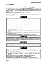
A 3-3 Printer Disassembly Procedures Rev. CAUTION Read CAUTION in Section 3.1.1 prior to disassembling the printer. Figure 3-1. EPSON Stylus COLOR 3000 3.2 Disassembly and Assembly This section describes procedures for disassembling and assembling the major units and parts.
A 3-3 Printer Disassembly Procedures Rev. CAUTION Read CAUTION in Section 3.1.1 prior to disassembling the printer. Figure 3-1. EPSON Stylus COLOR 3000 3.2 Disassembly and Assembly This section describes procedures for disassembling and assembling the major units and parts.

Service Manual
Page 73
Open the ink cartridge cover and release the hooks fixing the panel unit to the printer mechanism. Panel Unit Removal 3-4 Rev. Remove the knob, tip of the tractor unit. Then remove the tractor unit by inserting the tweezers into the cutouts in the illustrated part of the panel unit. A Disassembly and Assembly 3.2.1 Upper Housing...
Open the ink cartridge cover and release the hooks fixing the panel unit to the printer mechanism. Panel Unit Removal 3-4 Rev. Remove the knob, tip of the tractor unit. Then remove the tractor unit by inserting the tweezers into the cutouts in the illustrated part of the panel unit. A Disassembly and Assembly 3.2.1 Upper Housing...

Service Manual
Page 75
Remove the ROM. Remove 2 screws securing the ROM cover to disconnect the power cable from the AC socket before replacing the ROM. 3-6 Rev. CAUTION Be sure to the bottom of the lower housing and remove the ROM cover. 2. A Disassembly and Assembly 3.2.2 ROM Replacement 1.
Remove the ROM. Remove 2 screws securing the ROM cover to disconnect the power cable from the AC socket before replacing the ROM. 3-6 Rev. CAUTION Be sure to the bottom of the lower housing and remove the ROM cover. 2. A Disassembly and Assembly 3.2.2 ROM Replacement 1.

Service Manual
Page 76
Note) If the any ink cartridge is installed, remove it up. 5. EPSON Stylus COLOR 3000 3.2.3 CR PW (Paper Width) Sensor Board Assembly Removal 1. Remove the damper cover. 4. A 3-7 Remove 2 screw (CBP, 3X8) and 2 plain washer (3X0.5X7) securing the damper cover... black head cable. Remove the upper housing. (See Section 3.2.1.) 2. Then remove the CR PW sensor cover covering the black and color cables by pulling it to avoid ink leakage during disassembly and assembly. 3. CR PW Sensor Board Assembly Removal Rev. Inset tweezers into the small cutout inside the CR unit to the...
Note) If the any ink cartridge is installed, remove it up. 5. EPSON Stylus COLOR 3000 3.2.3 CR PW (Paper Width) Sensor Board Assembly Removal 1. Remove the damper cover. 4. A 3-7 Remove 2 screw (CBP, 3X8) and 2 plain washer (3X0.5X7) securing the damper cover... black head cable. Remove the upper housing. (See Section 3.2.1.) 2. Then remove the CR PW sensor cover covering the black and color cables by pulling it to avoid ink leakage during disassembly and assembly. 3. CR PW Sensor Board Assembly Removal Rev. Inset tweezers into the small cutout inside the CR unit to the...

Service Manual
Page 77
... cables. 8. Remove 2 screw (CBP, 3X8) and 2 plain washer (3X0.5X7) securing the damper cover to avoid ink leakage during disassembly and assembly. 3. Remove each color tube to catch the color head cable. A Then release the black and color head cables. (See Section 3.2.3.) 5. REQUIRED ADJUSTMENT After replacing the head, perform necessary adjustments. (See Chapter 4.) 3-8 Rev. Remove...
... cables. 8. Remove 2 screw (CBP, 3X8) and 2 plain washer (3X0.5X7) securing the damper cover to avoid ink leakage during disassembly and assembly. 3. Remove each color tube to catch the color head cable. A Then release the black and color head cables. (See Section 3.2.3.) 5. REQUIRED ADJUSTMENT After replacing the head, perform necessary adjustments. (See Chapter 4.) 3-8 Rev. Remove...

Service Manual
Page 79
A Disassembly and Assembly 3.2.5 HP Sensor Removal 1. Using tweezers, release the hook securing the HP sensor to the HP sensor holder and remove the HP sensor. Figure 3-7. Remove the upper housing. (See Section 3.2.1.) 2. HP Sensor Removal 3-10 Rev. Disconnect the connector cable for the HP sensor from the sensor connector. 3.
A Disassembly and Assembly 3.2.5 HP Sensor Removal 1. Using tweezers, release the hook securing the HP sensor to the HP sensor holder and remove the HP sensor. Figure 3-7. Remove the upper housing. (See Section 3.2.1.) 2. HP Sensor Removal 3-10 Rev. Disconnect the connector cable for the HP sensor from the sensor connector. 3.

Service Manual
Page 81
A Disassembly and Assembly 3.2.7 PSB/PSE Board Assembly Removal 1. Disconnect the power cable and connector cable for the main board assembly from the CN1 for about 5 minutes, ... Board Removal Rev. WARNING After disconnecting the power cable from the AC socket, never disconnect the cable from the CN1 and CN2, respectively. 5. Remove the printer mechanism unit. (See Section 3.2.6.) 3. Remove 7 screws (6 CBS screws , 3X8 and 1 CBP screw, 3X12) securing the upper shield plate to the lower housing, then remove the...
A Disassembly and Assembly 3.2.7 PSB/PSE Board Assembly Removal 1. Disconnect the power cable and connector cable for the main board assembly from the CN1 for about 5 minutes, ... Board Removal Rev. WARNING After disconnecting the power cable from the AC socket, never disconnect the cable from the CN1 and CN2, respectively. 5. Remove the printer mechanism unit. (See Section 3.2.6.) 3. Remove 7 screws (6 CBS screws , 3X8 and 1 CBP screw, 3X12) securing the upper shield plate to the lower housing, then remove the...

Service Manual
Page 83
Disassembly and Assembly 3-14 Figure 3-10. C203 MAIN board Removal Rev. A
Disassembly and Assembly 3-14 Figure 3-10. C203 MAIN board Removal Rev. A

Service Manual
Page 85
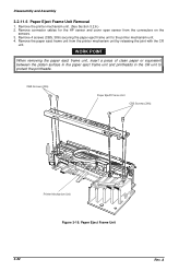
Using tweezers, release 3 hooks securing the PL sensors to the cable length which locates the proper connector. Remove the printer mechanism unit. (See Section 3.2.6.) 3. Disconnect the connector cable for the PL sensor from the CN11 on the main board assembly. 4. WORK POINT Make sure you connect each connector cable to the appropriate connector paying attention to the lower housing. Figure 3-12. PL Sensor Removal 3-16 Rev. A Remove the upper housing. (See section 3.2.1.) 2. Disassembly and Assembly 3.2.10 PL (Paper Length) Sensor Removal 1.
Using tweezers, release 3 hooks securing the PL sensors to the cable length which locates the proper connector. Remove the printer mechanism unit. (See Section 3.2.6.) 3. Disconnect the connector cable for the PL sensor from the CN11 on the main board assembly. 4. WORK POINT Make sure you connect each connector cable to the appropriate connector paying attention to the lower housing. Figure 3-12. PL Sensor Removal 3-16 Rev. A Remove the upper housing. (See section 3.2.1.) 2. Disassembly and Assembly 3.2.10 PL (Paper Length) Sensor Removal 1.

Service Manual
Page 86
...frame assembly. A Figure 3-14. CR Motor Removal CAUTION CR motor fan and CR motor assembly are 2 separate parts. EPSON Stylus COLOR 3000 3.2.11 Printer Mechanism Disassembly Section 3.2.11.1 thorough to Section 3.2.11.18 describe procedures for the CR motor and base frame assembly by turning the motor... the bottom edge of the CR motor shaft, as shown in Figure 3-14. Release the joint for printer mechanism unit disassembly. 3.2.11.1 CR Motor Removal 1. Rev. Remove the printer mechanism unit. (See Section 3.2.6.) 2. Therefore be sure to loosen the timing belt. 3. Dismount the...
...frame assembly. A Figure 3-14. CR Motor Removal CAUTION CR motor fan and CR motor assembly are 2 separate parts. EPSON Stylus COLOR 3000 3.2.11 Printer Mechanism Disassembly Section 3.2.11.1 thorough to Section 3.2.11.18 describe procedures for the CR motor and base frame assembly by turning the motor... the bottom edge of the CR motor shaft, as shown in Figure 3-14. Release the joint for printer mechanism unit disassembly. 3.2.11.1 CR Motor Removal 1. Rev. Remove the printer mechanism unit. (See Section 3.2.6.) 2. Therefore be sure to loosen the timing belt. 3. Dismount the...

Service Manual
Page 87
Pump Motor Assembly Removal 3-18 Rev. Remove 2 screws (CBS, 3x6) securing the pump motor assembly to the printer mechanism unit from the clump. 3. Disassembly and Assembly 3.2.11.2 Pump Motor Assembly Removal 1. A Then remove the pump motor assembly. Remove the connector cable for the pump motor assembly securing the pump motor to the sub frame assembly. Figure 3-15. Remove the printer mechanism unit. (See Section 3.2.6.) 2.
Pump Motor Assembly Removal 3-18 Rev. Remove 2 screws (CBS, 3x6) securing the pump motor assembly to the printer mechanism unit from the clump. 3. Disassembly and Assembly 3.2.11.2 Pump Motor Assembly Removal 1. A Then remove the pump motor assembly. Remove the connector cable for the pump motor assembly securing the pump motor to the sub frame assembly. Figure 3-15. Remove the printer mechanism unit. (See Section 3.2.6.) 2.

Service Manual
Page 89
Remove the printer mechanism unit. (See Section 3.2.6.) 2. Then remove the sensors. 3. A Using tweezers, release 2 hooks securing the front and rear PE sensors to the rear paper guide assembly at the bottom of the printer mechanism unit. Figure 3-17. Front/Rear PE Sensor Removal 3-20 Rev. Disconnect the sensor connector cables from the sensor connectors. Disassembly and Assembly 3.2.11.4 Front/Rear PE Sensor Removal 1.
Remove the printer mechanism unit. (See Section 3.2.6.) 2. Then remove the sensors. 3. A Using tweezers, release 2 hooks securing the front and rear PE sensors to the rear paper guide assembly at the bottom of the printer mechanism unit. Figure 3-17. Front/Rear PE Sensor Removal 3-20 Rev. Disconnect the sensor connector cables from the sensor connectors. Disassembly and Assembly 3.2.11.4 Front/Rear PE Sensor Removal 1.
Service Manual
Page 91
..., 3X6) securing the paper eject frame unit to protect the printheads. 3-22 Figure 3-19. Remove the printer mechanism unit. (See Section 3.2.6.) 2. A Remove connector cables for the HP sensor and cover open sensor from the printer mechanism unit by releasing the joint with the CR unit. WORK POINT When removing the paper eject..., insert a piece of clean paper or equivalent between the platen surface in the paper eject frame unit and printheads in the CR unit to the printer mechanism unit. 4. Disassembly and Assembly 3.2.11.6 Paper Eject Frame Unit Removal 1.
..., 3X6) securing the paper eject frame unit to protect the printheads. 3-22 Figure 3-19. Remove the printer mechanism unit. (See Section 3.2.6.) 2. A Remove connector cables for the HP sensor and cover open sensor from the printer mechanism unit by releasing the joint with the CR unit. WORK POINT When removing the paper eject..., insert a piece of clean paper or equivalent between the platen surface in the paper eject frame unit and printheads in the CR unit to the printer mechanism unit. 4. Disassembly and Assembly 3.2.11.6 Paper Eject Frame Unit Removal 1.

Service Manual
Page 93
...nut under the cartridge holder will be removed easily in the next step. 5. Figure 3-21. Disassembly and Assembly 3.2.11.8 Edge Guide Unit Removal 1. Disconnect the connector cable for the slide covers ... Rev. A Then remove the edge guide unit. Remove 1 screw (CBS, 3X8) securing the ink cartridge holder to the left frame assembly and middle frame unit. Release the joints for the PQ...right edge guide. 4. Remove the printer mechanism unit. (See Section 3.2.6.) 2. Edge Guide Unit Removal WORK POINT When installing the edge guide unit to the printer mechanism unit, engage the rack ...
...nut under the cartridge holder will be removed easily in the next step. 5. Figure 3-21. Disassembly and Assembly 3.2.11.8 Edge Guide Unit Removal 1. Disconnect the connector cable for the slide covers ... Rev. A Then remove the edge guide unit. Remove 1 screw (CBS, 3X8) securing the ink cartridge holder to the left frame assembly and middle frame unit. Release the joints for the PQ...right edge guide. 4. Remove the printer mechanism unit. (See Section 3.2.6.) 2. Edge Guide Unit Removal WORK POINT When installing the edge guide unit to the printer mechanism unit, engage the rack ...

Service Manual
Page 95
Remove the printer mechanism unit. (See Section 3.2.6.) 2. Remove the edge guide unit. (See Section 3.2.11.8.) 3. PQ Sensor Removal 3-26 Rev. Remove 1 pan camera 1B tight screw (2X3.5) securing ... threads of the tapped holes in the edge guide unit might crush. Figure 3-23. CAUTION Do not apply too much torque when tightening the screws. Disassembly and Assembly 3.2.11.9 PQ (Paper Quantity) Sensor Board Assembly Removal 1. A Remove 2 pan camera screws (2X5.5) securing the PQ sensor cover to the right edge guide...
Remove the printer mechanism unit. (See Section 3.2.6.) 2. Remove the edge guide unit. (See Section 3.2.11.8.) 3. PQ Sensor Removal 3-26 Rev. Remove 1 pan camera 1B tight screw (2X3.5) securing ... threads of the tapped holes in the edge guide unit might crush. Figure 3-23. CAUTION Do not apply too much torque when tightening the screws. Disassembly and Assembly 3.2.11.9 PQ (Paper Quantity) Sensor Board Assembly Removal 1. A Remove 2 pan camera screws (2X5.5) securing the PQ sensor cover to the right edge guide...


