
Software User Guide
Page 113
...density • Print speed 3 Click the [Set] button. Configure as a sudden power shutoff during printing, lower the [Power Supply Unit Capacity] level. Make sure you test print after changing the width. • If a power‐related trouble occurs, such as follows. 1 Click the [Printing Control] menu. ...mm, attach the Roll Paper Guide to the printer. 113 Print speed: Selects the print speed. Power Supply Unit Capacity: Selects the capacity level of the power supply unit connected to the printer. • When you make any of the following printing control items. ...
...density • Print speed 3 Click the [Set] button. Configure as a sudden power shutoff during printing, lower the [Power Supply Unit Capacity] level. Make sure you test print after changing the width. • If a power‐related trouble occurs, such as follows. 1 Click the [Printing Control] menu. ...mm, attach the Roll Paper Guide to the printer. 113 Print speed: Selects the print speed. Power Supply Unit Capacity: Selects the capacity level of the power supply unit connected to the printer. • When you make any of the following printing control items. ...

Reference Guide
Page 8
■ Option Specifications ...34 Power Supply Unit (PS-180) ...34 Setup 35 ■ Flow of Setup...35 ■ Installing the Printer...36 Important Notes on Horizontal Installation 36 Important Notes on ... For Ethernet/Wireless LAN/USB Interface 44 Selecting the Print Density (DIP Switches 2-3/2-4 45 Selecting the BUSY Status ...46 ■ Connecting the Power Supply Unit (PS-180 47 Connecting the Power Supply Unit ...47 ■ Setting the Memory Switches (Customized Value)48 Functions ...49 ■ Adjusting the Paper Roll Near-End Sensor 53...
■ Option Specifications ...34 Power Supply Unit (PS-180) ...34 Setup 35 ■ Flow of Setup...35 ■ Installing the Printer...36 Important Notes on Horizontal Installation 36 Important Notes on ... For Ethernet/Wireless LAN/USB Interface 44 Selecting the Print Density (DIP Switches 2-3/2-4 45 Selecting the BUSY Status ...46 ■ Connecting the Power Supply Unit (PS-180 47 Connecting the Power Supply Unit ...47 ■ Setting the Memory Switches (Customized Value)48 Functions ...49 ■ Adjusting the Paper Roll Near-End Sensor 53...
Reference Guide
Page 9
... Feed ...96 Receive Buffer ...96 Memory Capacity ...96 Electrical Characteristics ...96 DIP Switches ...97 Printer Status ...97 Logo Registration ...97 Driver Compatibility...97 USB Low Power Consumption Mode 98 Maintenance Counter ...98 Buzzer ...98 Power Supply Box ...98 Overall Dimensions ...99 9
... Feed ...96 Receive Buffer ...96 Memory Capacity ...96 Electrical Characteristics ...96 DIP Switches ...97 Printer Status ...97 Logo Registration ...97 Driver Compatibility...97 USB Low Power Consumption Mode 98 Maintenance Counter ...98 Buzzer ...98 Power Supply Box ...98 Overall Dimensions ...99 9
Reference Guide
Page 15
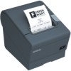
...Power supply box (Model: OT-BX88V) • Affixing tape for the roll paper guide* • The TM-T88V Software & Documents Disc (drivers, utilities, and documentation) * • Warranty certificate* • Setup Guide or User's manual * May not be included depending on the model. Chapter 1 Product Overview Colors • ECW (Epson... Cool White) • EDG (Epson Dark Gray) Accessories Included • Roll paper (for operation check) • Power switch cover 1 • Connector cover • Roll paper ...
...Power supply box (Model: OT-BX88V) • Affixing tape for the roll paper guide* • The TM-T88V Software & Documents Disc (drivers, utilities, and documentation) * • Warranty certificate* • Setup Guide or User's manual * May not be included depending on the model. Chapter 1 Product Overview Colors • ECW (Epson... Cool White) • EDG (Epson Dark Gray) Accessories Included • Roll paper (for operation check) • Power switch cover 1 • Connector cover • Roll paper ...

Reference Guide
Page 16
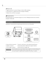
... saved every two minutes.) For detailed information about ESC/POS commands, see the ESC/POS Application Programming Guide. 16 If you use the power-off command to the power supply. Before turning the printer off, it is connected to the printer. The marks on the switch: ( : OFF/ : ON) CAUTION Before turning on or...
... saved every two minutes.) For detailed information about ESC/POS commands, see the ESC/POS Application Programming Guide. 16 If you use the power-off command to the power supply. Before turning the printer off, it is connected to the printer. The marks on the switch: ( : OFF/ : ON) CAUTION Before turning on or...

Reference Guide
Page 17
... the appearance of the printer may cause fire or shock. 1 Control Panel (Power) LED Error LED Paper LED Feed button LEDs Power LED (green) • Lights when the power supply is on. • Goes out when the power supply is turned on page 20.) • Goes out during regular operation (online).... 17 To reset the printer when the power switch cover is detected, and when ...
... the appearance of the printer may cause fire or shock. 1 Control Panel (Power) LED Error LED Paper LED Feed button LEDs Power LED (green) • Lights when the power supply is on. • Goes out when the power supply is turned on page 20.) • Goes out during regular operation (online).... 17 To reset the printer when the power switch cover is detected, and when ...
Reference Guide
Page 18
...Off when there is in /UB) Ethernet interface USB Plus Power • Drawer kick-out connector: • Interface connector: • Power supply connector: Connects a cash drawer or the optional external buzzer. Connects the power supply unit The picture above shows a serial interface model. For ...when a self-test is a sufficient amount of the printer. Drawer kick-out (DK) Serial interface Parallel interface ç Power supply USB interface (Built-in progress. Connects the printer with the host computer interface. Feed button Pressing this button down feeds the roll...
...Off when there is in /UB) Ethernet interface USB Plus Power • Drawer kick-out connector: • Interface connector: • Power supply connector: Connects a cash drawer or the optional external buzzer. Connects the power supply unit The picture above shows a serial interface model. For ...when a self-test is a sufficient amount of the printer. Drawer kick-out (DK) Serial interface Parallel interface ç Power supply USB interface (Built-in progress. Connects the printer with the host computer interface. Feed button Pressing this button down feeds the roll...
Reference Guide
Page 21
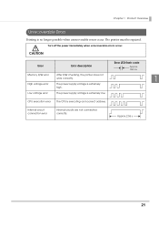
...Error LED flash code Approx. 160 ms Memory R/W error After R/W checking, the printer does not work correctly. 1 High voltage error The power supply voltage is extremely low. The printer must be repaired. Approx.2.56 s 21 CPU execution error The CPU is no longer possible when unrecoverable ...errors occur. Internal circuit connection error Internal circuits are not connected correctly. Turn off the power immediately when unrecoverable errors occur. Chapter 1 Product Overview Unrecoverable Errors Printing is executing an incorrect address.
...Error LED flash code Approx. 160 ms Memory R/W error After R/W checking, the printer does not work correctly. 1 High voltage error The power supply voltage is extremely low. The printer must be repaired. Approx.2.56 s 21 CPU execution error The CPU is no longer possible when unrecoverable ...errors occur. Internal circuit connection error Internal circuits are not connected correctly. Turn off the power immediately when unrecoverable errors occur. Chapter 1 Product Overview Unrecoverable Errors Printing is executing an incorrect address.
Reference Guide
Page 23
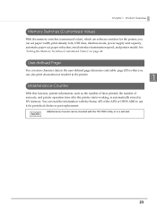
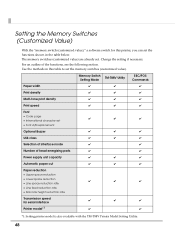
... data in the user-defined page (character code table: page 255) so that you can set paper width, print density, font, USB class, interface mode, power supply unit capacity, automatic paper cut, paper reduction, serial interface transmission speed, and printer model.
... data in the user-defined page (character code table: page 255) so that you can set paper width, print density, font, USB class, interface mode, power supply unit capacity, automatic paper cut, paper reduction, serial interface transmission speed, and printer model.
Reference Guide
Page 34
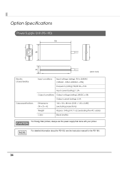
Option Specifications Power Supply Unit (PS-180) 136 68 33 [Unit: mm] Electric characteristics Case specifications Input conditions Input voltage (rating): 90 to 264VAC (100VAC -10% to 230VAC +15%) ...; 1.30 × 2.68"} (excluding projections) Weight Approx. 0.4 kg {14.11 oz} (excluding the AC cable) Color Black (matte) For Energy Star printers, always use the power supply that came with your printer. For detailed information about the PS-180, see the instruction manual for the PS-180. 34
Option Specifications Power Supply Unit (PS-180) 136 68 33 [Unit: mm] Electric characteristics Case specifications Input conditions Input voltage (rating): 90 to 264VAC (100VAC -10% to 230VAC +15%) ...; 1.30 × 2.68"} (excluding projections) Weight Approx. 0.4 kg {14.11 oz} (excluding the AC cable) Color Black (matte) For Energy Star printers, always use the power supply that came with your printer. For detailed information about the PS-180, see the instruction manual for the PS-180. 34
Reference Guide
Page 35
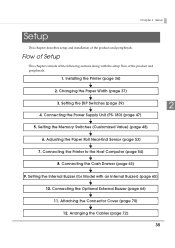
... chapter describes setup and installation of the product and peripherals. 1. Connecting the Cash Drawer (page 63) 9. Attaching the Connector Cover (page 70) 12. Connecting the Power Supply Unit (PS-180) (page 47) 5. Installing the Printer (page 36) 2. Setting the Memory Switches (Customized Value) (page 48) 6. Setting the Internal Buzzer (for Model with...
... chapter describes setup and installation of the product and peripherals. 1. Connecting the Cash Drawer (page 63) 9. Attaching the Connector Cover (page 70) 12. Connecting the Power Supply Unit (PS-180) (page 47) 5. Installing the Printer (page 36) 2. Setting the Memory Switches (Customized Value) (page 48) 6. Setting the Internal Buzzer (for Model with...
Reference Guide
Page 39
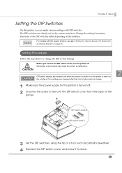
... printer. Setting Procedure Follow the steps below to malfunction. If the settings are enabled only when the power is turned off . Otherwise, a short-circuit may cause the printer to change . 1 Make sure the power supply for the current interfaces. CAUTION 2 DIP switch settings are changed after that, the functions will not change...
... printer. Setting Procedure Follow the steps below to malfunction. If the settings are enabled only when the power is turned off . Otherwise, a short-circuit may cause the printer to change . 1 Make sure the power supply for the current interfaces. CAUTION 2 DIP switch settings are changed after that, the functions will not change...
Reference Guide
Page 47
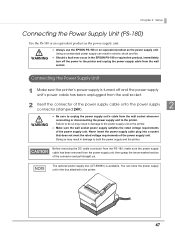
... result in the box attached to the power supply unit or the printer. Make sure the wall socket power supply satisfies the rated voltage requirements of the power supply cable onto the power supply 2 connector (stamped 24V). WARNING Always use the EPSON PS-180 or an equivalent product as the power supply unit. You can result in electric shock...
... result in the box attached to the power supply unit or the printer. Make sure the wall socket power supply satisfies the rated voltage requirements of the power supply cable onto the power supply 2 connector (stamped 24V). WARNING Always use the EPSON PS-180 or an equivalent product as the power supply unit. You can result in electric shock...
Reference Guide
Page 48
... table below. The memory switches (customized value) are already set the memory switches (customized value). For an outline of head energizing parts ✔ ✔ Power supply unit capacity ✔ ✔ ✔ Automatic paper cut ✔ ✔ ✔ Paper reduction Upper space reduction Lower space reduction Line space reduction...
... table below. The memory switches (customized value) are already set the memory switches (customized value). For an outline of head energizing parts ✔ ✔ Power supply unit capacity ✔ ✔ ✔ Automatic paper cut ✔ ✔ ✔ Paper reduction Upper space reduction Lower space reduction Line space reduction...
Reference Guide
Page 52
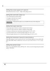
Setting the power supply unit capacity Selectable from levels 1 to 3 (Low High) (initial setting: level 3) Setting the automatic paper cut • Not use this function (initial setting) • ...
Setting the power supply unit capacity Selectable from levels 1 to 3 (Low High) (initial setting: level 3) Setting the automatic paper cut • Not use this function (initial setting) • ...
Reference Guide
Page 55
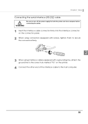
Chapter 2 Setup Connecting the serial interface (RS-232) cable WARNING Be sure to turn off the power supply for both the printer and host computer before connecting the cables. 1 Insert the interface cable connector firmly into the interface connector on the connector panel. 2 When using connectors equipped with screws, tighten them to secure the connectors firmly. 2 3 When using interface cables equipped with a grounding line, attach the ground line to the screw hole marked "FG" on the printer. 4 Connect the other end of the interface cable to the host computer. 55
Chapter 2 Setup Connecting the serial interface (RS-232) cable WARNING Be sure to turn off the power supply for both the printer and host computer before connecting the cables. 1 Insert the interface cable connector firmly into the interface connector on the connector panel. 2 When using connectors equipped with screws, tighten them to secure the connectors firmly. 2 3 When using interface cables equipped with a grounding line, attach the ground line to the screw hole marked "FG" on the printer. 4 Connect the other end of the interface cable to the host computer. 55
Reference Guide
Page 63
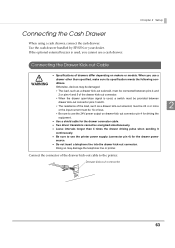
.... Use the cash drawer handled by EPSON or your dealer. If the optional external buzzer is used, a switch must be provided between pins 4 and 2 or pins 4 and 5 of the drawer kick-out cable to use the printer power supply (connector pin 4) for the drawer connector cable...61623; Specifications of drawers differ depending on drawer-kick out connector pin 4 for driving the equipment. Use a shield cable for the drawer power source. Do not insert a telephone line into the drawer kick-out connector. Doing so may be damaged. The load, ...
.... Use the cash drawer handled by EPSON or your dealer. If the optional external buzzer is used, a switch must be provided between pins 4 and 2 or pins 4 and 5 of the drawer kick-out cable to use the printer power supply (connector pin 4) for the drawer connector cable...61623; Specifications of drawers differ depending on drawer-kick out connector pin 4 for driving the equipment. Use a shield cable for the drawer power source. Do not insert a telephone line into the drawer kick-out connector. Doing so may be damaged. The load, ...
Reference Guide
Page 88
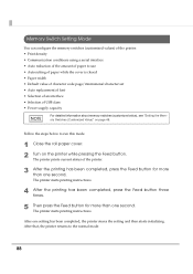
After that, the printer returns to the normal mode. 88 The printer prints current status of USB class • Power supply capacity For detailed information about memory switches (customized value), see "Setting the Memory Switches (Customized Value)" on the printer while pressing the Feed button. The ...
After that, the printer returns to the normal mode. 88 The printer prints current status of USB class • Power supply capacity For detailed information about memory switches (customized value), see "Setting the Memory Switches (Customized Value)" on the printer while pressing the Feed button. The ...
Reference Guide
Page 94
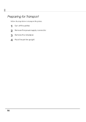
Preparing for Transport Follow the steps below to transport the printer. 1 Turn off the printer. 2 Remove the power supply connector. 3 Remove the roll paper. 4 Pack the printer upright. 94
Preparing for Transport Follow the steps below to transport the printer. 1 Turn off the printer. 2 Remove the power supply connector. 3 Remove the roll paper. 4 Pack the printer upright. 94
Reference Guide
Page 98
Power Supply Box The optional power supply box (OT-BX88V) is available with a built-in buzzer or without the buzzer, you...detailed information about ESC/POS commands, see the ESC/POS Application Programming Guide. USB Low Power Consumption Mode With the TM-T88V, you can enable the USB low power consumption mode with DIP Switch 1-8, just as you can beep the buzzer with the ...Buzzer (for the TM-T88IV. 98 Buzzer TM-T88V is available to be attached under the TM-T88V to hold the power unit, just as the OT-BX88 has been available for Model with an Internal Buzzer)" on page 65, "Connecting ...
Power Supply Box The optional power supply box (OT-BX88V) is available with a built-in buzzer or without the buzzer, you...detailed information about ESC/POS commands, see the ESC/POS Application Programming Guide. USB Low Power Consumption Mode With the TM-T88V, you can enable the USB low power consumption mode with DIP Switch 1-8, just as you can beep the buzzer with the ...Buzzer (for the TM-T88IV. 98 Buzzer TM-T88V is available to be attached under the TM-T88V to hold the power unit, just as the OT-BX88 has been available for Model with an Internal Buzzer)" on page 65, "Connecting ...