Installation Guide
Page 2
EPSON and ESC/POS are registered trademarks of Microsoft Corporation. CE Marking The display conforms to the following standards are applied only to comply with Seiko Epson Corporation's operating and maintenance instructions. EMC and Safety Standards Applied Product Name: DM-D500 Model Name: M151A The following Directives and Norms: Directive 89/336/EEC EN 55022 Class B EN 55024 IEC 61000-4-2 IEC...
EPSON and ESC/POS are registered trademarks of Microsoft Corporation. CE Marking The display conforms to the following standards are applied only to comply with Seiko Epson Corporation's operating and maintenance instructions. EMC and Safety Standards Applied Product Name: DM-D500 Model Name: M151A The following Directives and Norms: Directive 89/336/EEC EN 55022 Class B EN 55024 IEC 61000-4-2 IEC...
Installation Guide
Page 3
...damage and fire. Continued use may lead to fall into this equipment, immediately turn the power off and contact your dealer or a SEIKO EPSON service center for advice. Immediately turn beyond the limits of the display. Improper repair work can be damaged or...DM-D500 Installation Guide 1 Tampering with this product may be dangerous. If water or other liquid spills into the equipment. Be sure to fire or shock. WARNING: Shut down your dealer or a SEIKO EPSON service center for advice. Do not attach more than one extension support. Never attempt to an improper power...
...damage and fire. Continued use may lead to fall into this equipment, immediately turn the power off and contact your dealer or a SEIKO EPSON service center for advice. Immediately turn beyond the limits of the display. Improper repair work can be damaged or...DM-D500 Installation Guide 1 Tampering with this product may be dangerous. If water or other liquid spills into the equipment. Be sure to fire or shock. WARNING: Shut down your dealer or a SEIKO EPSON service center for advice. Do not attach more than one extension support. Never attempt to an improper power...
Installation Guide
Page 4
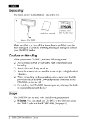
..., contact your DM-D500 dealer. Cautions on Handling When you use the DM-D500, note the following equipment. ❏ IR Series. Usage The DM-D500 can attach the DM-D500 to the DM-D500 are in illustration 1 are turned off. ❏ Do not drop the DM-D500, because you may damage the builtin vacuum fluorescent display. English Unpacking The items shown in the box. 1 installation manual warranty card (201 model only) display (DM-D500) Make sure that...
..., contact your DM-D500 dealer. Cautions on Handling When you use the DM-D500, note the following equipment. ❏ IR Series. Usage The DM-D500 can attach the DM-D500 to the DM-D500 are in illustration 1 are turned off. ❏ Do not drop the DM-D500, because you may damage the builtin vacuum fluorescent display. English Unpacking The items shown in the box. 1 installation manual warranty card (201 model only) display (DM-D500) Make sure that...

Installation Guide
Page 5
... DM-D stand, an optional power supply unit (PS-170) is one of the numbers listed in the table, the DM-D500 requires the latest model of the TM printer. English ❏ TM-H5000II and TM-J8000 printers. You can be connected to TM-H6000 and TM-U675 printers using the "DM-D pole unit for TM printers (Type A)" (DP-502). (See page 8.) ❏ TM-H6000 and TM-U675 printers. DM-D500 Installation Guide...
... DM-D stand, an optional power supply unit (PS-170) is one of the numbers listed in the table, the DM-D500 requires the latest model of the TM printer. English ❏ TM-H5000II and TM-J8000 printers. You can be connected to TM-H6000 and TM-U675 printers using the "DM-D pole unit for TM printers (Type A)" (DP-502). (See page 8.) ❏ TM-H6000 and TM-U675 printers. DM-D500 Installation Guide...
Installation Guide
Page 6
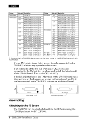
...the RS-232 interface of the UB-S01 before using it can be connected to the IR Series using the "DM-D pole unit for IR" (DP-504). 4 DM-D500 Installation Guide If your printer is a TM-H5000, always purchase the latest model of the TM printer or the UB-S01 board has a blue seal ...higher *1: If your TM printer is connected to the TM printer, purchase and install the latest model of the UB-S01 (Part code: C8233610000) is not listed above, it with the DM-D500. If an old model of the UB-S01 board (Part code: C8233610200). English Printer TM-H5000 TM-H5000II Model - 001 011 021 ...
...the RS-232 interface of the UB-S01 before using it can be connected to the IR Series using the "DM-D pole unit for IR" (DP-504). 4 DM-D500 Installation Guide If your printer is a TM-H5000, always purchase the latest model of the TM printer or the UB-S01 board has a blue seal ...higher *1: If your TM printer is connected to the TM printer, purchase and install the latest model of the UB-S01 (Part code: C8233610000) is not listed above, it with the DM-D500. If an old model of the UB-S01 board (Part code: C8233610200). English Printer TM-H5000 TM-H5000II Model - 001 011 021 ...

Installation Guide
Page 10
...) rubber feet (square) fixing screws fixing screws for rubber for metallic feet (large) portion fixing screws 20 support C support B for TM printers (Type A)" (DP-502). These items are used to attach a DM-D500 to a TM-U375 or TM-U950 printer. Connect the cable for the DM-D500 to a TM-U375 or TM-U950 printer using the "DM-D pole unit for extension fixing plate A 8 DM-D500 Installation Guide Required items The items shown in illustration 17. English 5.
...) rubber feet (square) fixing screws fixing screws for rubber for metallic feet (large) portion fixing screws 20 support C support B for TM printers (Type A)" (DP-502). These items are used to attach a DM-D500 to a TM-U375 or TM-U950 printer. Connect the cable for the DM-D500 to a TM-U375 or TM-U950 printer using the "DM-D pole unit for extension fixing plate A 8 DM-D500 Installation Guide Required items The items shown in illustration 17. English 5.
Installation Guide
Page 12
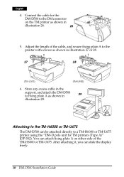
... for TM printers (Type A)" (DP-502). Store any excess cable in the support, and attach the DM-D500 to the DM connector on either side of the cable, and secure fixing plate A to a TM-H6000 or TM-U675 printer using the "DM-D pole unit for the DM-D500 to fixing plate A ...DM-D500 can be attached directly to the printer with screws as shown in illustration 27 or 28. 27 28 [TM-U375] [TM-U950] 6. You can slide the display freely. 10 DM-D500 Installation Guide After attaching it, you can attach fixing plate A on the TM printer as shown in illustration 26. 26 5. English...
... for TM printers (Type A)" (DP-502). Store any excess cable in the support, and attach the DM-D500 to the DM connector on either side of the cable, and secure fixing plate A to a TM-H6000 or TM-U675 printer using the "DM-D pole unit for the DM-D500 to fixing plate A ...DM-D500 can be attached directly to the printer with screws as shown in illustration 27 or 28. 27 28 [TM-U375] [TM-U950] 6. You can slide the display freely. 10 DM-D500 Installation Guide After attaching it, you can attach fixing plate A on the TM printer as shown in illustration 26. 26 5. English...
Installation Guide
Page 16
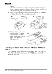
... the power cable of the display is not correct. To avoid 44 disconnection, hook the cable to a TM-T88II, TM-U210, TM-U230, TM-T90, or TM-L90 printer using the "DM-D pole unit for TM printers" (DP-505). 14 DM-D500 Installation Guide Attaching to fixing plate A as shown in illustration 43. 42 43 roll paper cover 9. Store any excess cable in the support...
... the power cable of the display is not correct. To avoid 44 disconnection, hook the cable to a TM-T88II, TM-U210, TM-U230, TM-T90, or TM-L90 printer using the "DM-D pole unit for TM printers" (DP-505). 14 DM-D500 Installation Guide Attaching to fixing plate A as shown in illustration 43. 42 43 roll paper cover 9. Store any excess cable in the support...
Installation Guide
Page 17
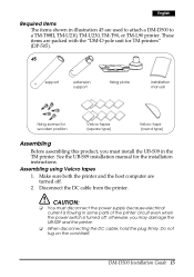
... parts of the printer circuit even when the power switch is turned off . 2. See the UB-S09 installation manual for wooden position Velcro tapes (square type) Velcro tape (round type) Assembling Before assembling this product, you may damage the UB-S09 and the printer. ❏ When disconnecting the DC cable, hold the plug firmly. Disconnect the DC cable from the printer. DM-D500 Installation Guide 15 English...
... parts of the printer circuit even when the power switch is turned off . 2. See the UB-S09 installation manual for wooden position Velcro tapes (square type) Velcro tape (round type) Assembling Before assembling this product, you may damage the UB-S09 and the printer. ❏ When disconnecting the DC cable, hold the plug firmly. Disconnect the DC cable from the printer. DM-D500 Installation Guide 15 English...

Installation Guide
Page 18
Pass the cable for the customer display through the hole on the support as shown in illustration 47 until you feel it click. 46 47 when using an extension support 4. English 3. When using the extension support, insert the tab on the extension support into the hole on the fixing plate, and attach the 48 support to the display as shown in illustration 46. Pass the cable for the display through the support, and attach the support to the fixing plate as shown in illustration 48. 16 DM-D500 Installation Guide
Pass the cable for the customer display through the hole on the support as shown in illustration 47 until you feel it click. 46 47 when using an extension support 4. English 3. When using the extension support, insert the tab on the extension support into the hole on the fixing plate, and attach the 48 support to the display as shown in illustration 46. Pass the cable for the display through the support, and attach the support to the fixing plate as shown in illustration 48. 16 DM-D500 Installation Guide

Installation Guide
Page 19
... shown in illustrations 49 and 50.) Printer type TM-T88II TM-U210/U230/T90/L90 Positioning number of the printer) Right side Left side Both sides 3 1 49 50 5 8 6 10 4 2 11 9 7 6. Store any excess cable in illustration 51. English 5. DM-D500 Installation Guide 17 Connect the cable for display (seen from the front of Velcro tape attachment 1 to 9 and 11 1 to 11...
... shown in illustrations 49 and 50.) Printer type TM-T88II TM-U210/U230/T90/L90 Positioning number of the printer) Right side Left side Both sides 3 1 49 50 5 8 6 10 4 2 11 9 7 6. Store any excess cable in illustration 51. English 5. DM-D500 Installation Guide 17 Connect the cable for display (seen from the front of Velcro tape attachment 1 to 9 and 11 1 to 11...

Installation Guide
Page 22
... using screws 1. Secure fixing plate A to the setting position. Assembling using Velcro tapes." 2. Follow steps 2 and 3 in illustration 58. 4. Peel off the Velcro tapes, and attach the display to the setting 61 position with fixing screws as 60 shown in illustration 61. 3. English 3. Pass the cable for the DM-D500 to fixing plate A. 20 DM-D500 Installation Guide Store any excess cable in the support, and attach the DM-D500 to fixing...
... using screws 1. Secure fixing plate A to the setting position. Assembling using Velcro tapes." 2. Follow steps 2 and 3 in illustration 58. 4. Peel off the Velcro tapes, and attach the display to the setting 61 position with fixing screws as 60 shown in illustration 61. 3. English 3. Pass the cable for the DM-D500 to fixing plate A. 20 DM-D500 Installation Guide Store any excess cable in the support, and attach the DM-D500 to fixing...

Installation Guide
Page 24
English Connectors for the DM-D stand The connectors for the RS-232C. computer connector display connector printer connector 65 power supply unit connector extension cable connector Note: The DM-D stand comes with the included millimeter-type screws using the DM-D stand as a standalone. (TM printer is not connected.) 22 DM-D500 Installation Guide notch (one or more lines) 66 inch-type millimeter-type Jumper settings Set the jumpers on the...
English Connectors for the DM-D stand The connectors for the RS-232C. computer connector display connector printer connector 65 power supply unit connector extension cable connector Note: The DM-D stand comes with the included millimeter-type screws using the DM-D stand as a standalone. (TM printer is not connected.) 22 DM-D500 Installation Guide notch (one or more lines) 66 inch-type millimeter-type Jumper settings Set the jumpers on the...

Installation Guide
Page 26
... 4. Connect the cable for the DM-D500 to fasten them. 72 computer 24 DM-D500 Installation Guide Connect one end of the cables to the display connector on the computer as shown in illustration 72. Insert the tab on the DM-D500 (or the extension support) into the hole on the DM-D stand; English 2. then connect the other end to the computer connector on...
... 4. Connect the cable for the DM-D500 to fasten them. 72 computer 24 DM-D500 Installation Guide Connect one end of the cables to the display connector on the computer as shown in illustration 72. Insert the tab on the DM-D500 (or the extension support) into the hole on the DM-D stand; English 2. then connect the other end to the computer connector on...

Installation Guide
Page 29
DM-D500 Installation Guide 27 Note: When turning on /off , wait for details. See "DIP Switch" for at least 3 seconds. Part Names and Functions Exterior 78 display English DIP switch (rear side of the display) power switch (bottom of the display) ❏ Display: Characters are displayed. ❏ Power switch: The power is turned on the DM-D500 again after turning it off . ❏ DIP switch: The functions of the DM-D500 are changed.
DM-D500 Installation Guide 27 Note: When turning on /off , wait for details. See "DIP Switch" for at least 3 seconds. Part Names and Functions Exterior 78 display English DIP switch (rear side of the display) power switch (bottom of the display) ❏ Display: Characters are displayed. ❏ Power switch: The power is turned on the DM-D500 again after turning it off . ❏ DIP switch: The functions of the DM-D500 are changed.

Installation Guide
Page 30
... OFF ON (*1) XON/XOFF is effective only when the DM-D500 is connected to a TM printer, be sure that the transmission speed matches that of the printer. 28 DM-D500 Installation Guide English DIP Switch DIP Switch Functions The DM-D500 has two groups of the DIP switches are as a standalone... speed (bps) 2400 4800 9600 19200 38400 57600 115200 *When the DM-D500 is connected as follows: DIP switch 1 DSW1 No. 1-1 1-2 1-3 1-4 1-5 1-6 1-7 1-8 Function Data receive error Hand shaking Data length Parity on or off Parity type Change transmission speed ON OFF Ignored Displays "?"
... OFF ON (*1) XON/XOFF is effective only when the DM-D500 is connected to a TM printer, be sure that the transmission speed matches that of the printer. 28 DM-D500 Installation Guide English DIP Switch DIP Switch Functions The DM-D500 has two groups of the DIP switches are as a standalone... speed (bps) 2400 4800 9600 19200 38400 57600 115200 *When the DM-D500 is connected as follows: DIP switch 1 DSW1 No. 1-1 1-2 1-3 1-4 1-5 1-6 1-7 1-8 Function Data receive error Hand shaking Data length Parity on or off Parity type Change transmission speed ON OFF Ignored Displays "?"

Installation Guide
Page 31
... TM printer and DM display. When setting to "Display is selected," data is displayed on the power. DM-D500 Installation Guide 29 English DIP switch 2 DSW2 No. 2-1 2-2 2-3 2-4 2-5 2-6 2-7 2-8 Function Y-connection (*1) Self test selection (*2) 20 column and 2 line mode selection (*3) Device selection default setting Address 0 Address 1 Address 2 Reserved (*5) ON OFF Enabled Perform self test 20 column and 2 line mode Printer is selected Disabled Do not perform 256 × 64 dots mode Display is selected Default setting...
... TM printer and DM display. When setting to "Display is selected," data is displayed on the power. DM-D500 Installation Guide 29 English DIP switch 2 DSW2 No. 2-1 2-2 2-3 2-4 2-5 2-6 2-7 2-8 Function Y-connection (*1) Self test selection (*2) 20 column and 2 line mode selection (*3) Device selection default setting Address 0 Address 1 Address 2 Reserved (*5) ON OFF Enabled Perform self test 20 column and 2 line mode Printer is selected Disabled Do not perform 256 × 64 dots mode Display is selected Default setting...

Installation Guide
Page 32
... "DM-D pole unit for IR" (DP-504) and the "DM-D pole unit for left and right) 30 DM-D500 Installation Guide If you move it any further if it . In this case, remove the base, change the position of the switches with a pointed object, such as shown in illustration 80. 45° for TM printers (Type B)" (DP-503), the display area may damage it stops. English 2. Remove...
... "DM-D pole unit for IR" (DP-504) and the "DM-D pole unit for left and right) 30 DM-D500 Installation Guide If you move it any further if it . In this case, remove the base, change the position of the switches with a pointed object, such as shown in illustration 80. 45° for TM printers (Type B)" (DP-503), the display area may damage it stops. English 2. Remove...

Installation Guide
Page 33
... test is finished and no error occurs, the cursor is ready to receive data. Set the SW 2-2 of the DIP switch 2 to perform a self test, you must change the setting of Self Test The following items are not displayed, the DM-D500 may be malfunctioning. English Self Test The DM-D500 has a self test function. Turn off the power for assistance. Check Items of the DIP switch.
... test is finished and no error occurs, the cursor is ready to receive data. Set the SW 2-2 of the DIP switch 2 to perform a self test, you must change the setting of Self Test The following items are not displayed, the DM-D500 may be malfunctioning. English Self Test The DM-D500 has a self test function. Turn off the power for assistance. Check Items of the DIP switch.

Installation Guide
Page 34
...-504: 60 g {0.13 lb}, DP-505: 418 g {0.92 lb} 32 DM-D500 Installation Guide English Specifications Tilt angle Horizontal rotation Vacuum fluorescent display Characters Character grid Character style Emulation mode Electrical specification Reliability Temperature Humidity Overall dimensions Weight (mass) Max. 48° (4 steps, 5 positions) Max. 90° (for each left and right at 45°) • Total number of dots: 256 × 64 (W × H) • Dot pitch...
...-504: 60 g {0.13 lb}, DP-505: 418 g {0.92 lb} 32 DM-D500 Installation Guide English Specifications Tilt angle Horizontal rotation Vacuum fluorescent display Characters Character grid Character style Emulation mode Electrical specification Reliability Temperature Humidity Overall dimensions Weight (mass) Max. 48° (4 steps, 5 positions) Max. 90° (for each left and right at 45°) • Total number of dots: 256 × 64 (W × H) • Dot pitch...


