Product Information Guide
Page 6
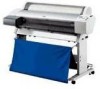
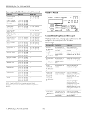
...epson.com) for your printer. Install ink cartridges as indicated by Ink Out light(s). You must install the cartridges that may become available. EPSON Stylus Pro 7600 and 9600 7/02 Radiant White 13" × 19": S041351 EPSON Velvet Fine - INK OUT Ink Out light(s) on Paper lever is available to finish cleaning the print head...light(s) flashing Ink cartridge(s) are empty (printing stops). Replace the ink cartridge(s) indicated by the lights. WRONG INK CARTRIDGE INVALID INK CARTRIDGE Ink Out light(s) on Not enough ink is in the released position (all the way forward, to ...
...epson.com) for your printer. Install ink cartridges as indicated by Ink Out light(s). You must install the cartridges that may become available. EPSON Stylus Pro 7600 and 9600 7/02 Radiant White 13" × 19": S041351 EPSON Velvet Fine - INK OUT Ink Out light(s) on Paper lever is available to finish cleaning the print head...light(s) flashing Ink cartridge(s) are empty (printing stops). Replace the ink cartridge(s) indicated by the lights. WRONG INK CARTRIDGE INVALID INK CARTRIDGE Ink Out light(s) on Not enough ink is in the released position (all the way forward, to ...
Product Information Guide
Page 7
... the message appears during the printing process or another operation. PAPER NOT CUT error was released during a print job, reset the printer by pressing the Pause button for about a minute, then turn the printer off. FRONT COVER OPEN Pause light on Front cover is the same on again. 7/02 EPSON Stylus Pro 7600 and 9600 - 8 correct driver for head cleaning.
... the message appears during the printing process or another operation. PAPER NOT CUT error was released during a print job, reset the printer by pressing the Pause button for about a minute, then turn the printer off. FRONT COVER OPEN Pause light on Front cover is the same on again. 7/02 EPSON Stylus Pro 7600 and 9600 - 8 correct driver for head cleaning.

User Manual
Page 105
... to release the queue and resume printing. See page 132 for the highlighted print job Click the print job whose priority you want to start the print head cleaning utility. Then click the Priority list box and select one of the following : • Double-click a file in the EPSON Monitor3 dialog box, select Start print queue from the Printer...
... to release the queue and resume printing. See page 132 for the highlighted print job Click the print job whose priority you want to start the print head cleaning utility. Then click the Priority list box and select one of the following : • Double-click a file in the EPSON Monitor3 dialog box, select Start print queue from the Printer...
Service Manual
Page 8
EPSON Stylus Pro 7600/9600 Revision A 3.2.2.13 Ink-related Errors 130 3.2.2.14 Defective ink cartridge 130 3.2.2.15 Ink lever released... 139 3.2.4.13 PF home position sensor error (0001000B 139 3.2.4.14 Head slide (PG) home position sensor error (0001000C 140 3.2.4.15 CR...right error (00010020 143 3.2.4.21 Ink type error (setting on printer body side) (00010022 143 3.2.4.22 RTC analysis error (00010023 143 ...3.3 Troubleshooting Based on Your Printout 147 3.3.1 Dot Missing 147 3.3.2 Uneven Printing/Poor Resolution 148 3.3.3 Smudged or Marred Printout (Front 148 3.3.4 Smudged or...
EPSON Stylus Pro 7600/9600 Revision A 3.2.2.13 Ink-related Errors 130 3.2.2.14 Defective ink cartridge 130 3.2.2.15 Ink lever released... 139 3.2.4.13 PF home position sensor error (0001000B 139 3.2.4.14 Head slide (PG) home position sensor error (0001000C 140 3.2.4.15 CR...right error (00010020 143 3.2.4.21 Ink type error (setting on printer body side) (00010022 143 3.2.4.22 RTC analysis error (00010023 143 ...3.3 Troubleshooting Based on Your Printout 147 3.3.1 Dot Missing 147 3.3.2 Uneven Printing/Poor Resolution 148 3.3.3 Smudged or Marred Printout (Front 148 3.3.4 Smudged or...

Service Manual
Page 9
EPSON Stylus Pro 7600/9600 Revision A 4.3 Disassembly and Assembly of Carriage (CR) Mechanism 171 4.3.1 Print Head 171 4.3.2 Damper ASSY 173 4.3.3 CR Board ASSY 174 4.3.4 Cutter Section 175 4.3.4.1 Cutter Holder ASSY 175 4.3.4.2 Cutter Solenoid 177...216 5.1.4.10 PF Encoder Sensor ASSY Adjustment 216 5.1.4.11 Cutter Solenoid ASSY or Paper Guide L Adjustment 217 5.1.4.12 Damper ASSY Adjustment 217 5.1.4.13 Release Sensor (I/H Lever) Adjustment 217 5.1.4.14 Battery 217 5.1.5 Parameter Backup 218 5.1.5.1 Parameter Backup Procedure 218 5.1.5.2 Work Procedure 218 5.1.5.3 Others 218 ...
EPSON Stylus Pro 7600/9600 Revision A 4.3 Disassembly and Assembly of Carriage (CR) Mechanism 171 4.3.1 Print Head 171 4.3.2 Damper ASSY 173 4.3.3 CR Board ASSY 174 4.3.4 Cutter Section 175 4.3.4.1 Cutter Holder ASSY 175 4.3.4.2 Cutter Solenoid 177...216 5.1.4.10 PF Encoder Sensor ASSY Adjustment 216 5.1.4.11 Cutter Solenoid ASSY or Paper Guide L Adjustment 217 5.1.4.12 Damper ASSY Adjustment 217 5.1.4.13 Release Sensor (I/H Lever) Adjustment 217 5.1.4.14 Battery 217 5.1.5 Parameter Backup 218 5.1.5.1 Parameter Backup Procedure 218 5.1.5.2 Work Procedure 218 5.1.5.3 Others 218 ...

Service Manual
Page 22
... function with "Paper Feed +/-" button if necessary. 5. otherwise, the head would be performed on the LCD panel. 4. Paper is fed L2 ...45%" fixed. Slide the cutter along the cutter guide to -print position (Paper is indicated on the approved media. † ... cut roll paper, automatic and manual cutting. After cutting, release the printer from the pause status by driver 4-step cut (200cps) ... than L2. EPSON Stylus Pro 7600/9600 1.2.6.2 Paper Set Lever Table 1-16. Paper edge waiting position is automatically fed toward the cutter guide, and printer becomes Off-line...
... function with "Paper Feed +/-" button if necessary. 5. otherwise, the head would be performed on the LCD panel. 4. Paper is fed L2 ...45%" fixed. Slide the cutter along the cutter guide to -print position (Paper is indicated on the approved media. † ... cut roll paper, automatic and manual cutting. After cutting, release the printer from the pause status by driver 4-step cut (200cps) ... than L2. EPSON Stylus Pro 7600/9600 1.2.6.2 Paper Set Lever Table 1-16. Paper edge waiting position is automatically fed toward the cutter guide, and printer becomes Off-line...

Service Manual
Page 32
...LEDs indicate printer status as follows: LED (color) Operate (Green) Paper Out (Red) Pause (Green) Ink Out (K1) (Red) Ink Out (K2) (Red) Ink Out (C) (Red) Ink Out (M) (Red) Ink Out (LC) (Red) Ink Out (LM) (Red) Table 1-21. Product Description Operating Panel 32 EPSON Stylus Pro 7600/9600 Note *1:...sheet, roll paper is not set lever is released, or paper is thick for another 2 seconds. 1.4.1.2 LEDs The printer is equipped with the following LEDs. Roll, Cutter off (Green) On Blink Roll, Cutter off is selected. Blink Cleaning print head, or ink drying. On Light cyan ink ...
...LEDs indicate printer status as follows: LED (color) Operate (Green) Paper Out (Red) Pause (Green) Ink Out (K1) (Red) Ink Out (K2) (Red) Ink Out (C) (Red) Ink Out (M) (Red) Ink Out (LC) (Red) Ink Out (LM) (Red) Table 1-21. Product Description Operating Panel 32 EPSON Stylus Pro 7600/9600 Note *1:...sheet, roll paper is not set lever is released, or paper is thick for another 2 seconds. 1.4.1.2 LEDs The printer is equipped with the following LEDs. Roll, Cutter off (Green) On Blink Roll, Cutter off is selected. Blink Cleaning print head, or ink drying. On Light cyan ink ...

Service Manual
Page 102
... Revision A Table 2-1. Table 2-1. EPSON Stylus Pro 7600/9600 2.2 Print Mechanism Components The major electrical parts used in the print head DC motor Transmission type photo-interrupter Linear encoder (180LPI) DC motor Reflection type photo-interrupter Reflection type photo-interrupter DC solenoid DC motor Linear encoder (360LPI) The number of this printer are as shown below. Printer Mechanism Components Drive...
... Revision A Table 2-1. Table 2-1. EPSON Stylus Pro 7600/9600 2.2 Print Mechanism Components The major electrical parts used in the print head DC motor Transmission type photo-interrupter Linear encoder (180LPI) DC motor Reflection type photo-interrupter Reflection type photo-interrupter DC solenoid DC motor Linear encoder (360LPI) The number of this printer are as shown below. Printer Mechanism Components Drive...

Service Manual
Page 107
...Pump motor runs forward by 10 pulses Pump motor runs forward until head slide origin sensor turns OFF No Slide Sensor OFF ? Head Slide (PG Change) Initialization Sequence Operating Principles Print Mechanism Components 107 The cam is detected. Pulse Positions Position Gap ...to pseudo-vacuum position Slide Sensor OFF Yes ? Yes After head slide origin sensor turns ON, pump motor runs forward by 18 pulses (till epicyclic gear release) End Figure 2-5. EPSON Stylus Pro 7600/9600 † HD_SLID (Head Gap Home Position Detection) Sensor This sensor detects the mechanical...
...Pump motor runs forward by 10 pulses Pump motor runs forward until head slide origin sensor turns OFF No Slide Sensor OFF ? Head Slide (PG Change) Initialization Sequence Operating Principles Print Mechanism Components 107 The cam is detected. Pulse Positions Position Gap ...to pseudo-vacuum position Slide Sensor OFF Yes ? Yes After head slide origin sensor turns ON, pump motor runs forward by 18 pulses (till epicyclic gear release) End Figure 2-5. EPSON Stylus Pro 7600/9600 † HD_SLID (Head Gap Home Position Detection) Sensor This sensor detects the mechanical...
Service Manual
Page 115
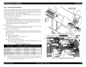
... of the printer. Table 2-6. The cleaning mechanism is located on (Suction, wiper setting) „ Counter clockwise rotation (CCW): Pump release, wiper reset, HD_SLIDE (head gap adjustment)... Mechanism Components Pump assembly Flushing box Head cleaner CR Lock Pump motor Cap assembly Figure 2-15. Cleaning Mechanism Components Operating Principles Print Mechanism Components 115 Pump Drive Modes ... in the Stylus Pro 5000/9000. The waste ink from the nozzles. EPSON Stylus Pro 7600/9600 2.2.3 Cleaning Mechanism The cleaning mechanism in this printer is compatible with P.C.D of φ...
... of the printer. Table 2-6. The cleaning mechanism is located on (Suction, wiper setting) „ Counter clockwise rotation (CCW): Pump release, wiper reset, HD_SLIDE (head gap adjustment)... Mechanism Components Pump assembly Flushing box Head cleaner CR Lock Pump motor Cap assembly Figure 2-15. Cleaning Mechanism Components Operating Principles Print Mechanism Components 115 Pump Drive Modes ... in the Stylus Pro 5000/9000. The waste ink from the nozzles. EPSON Stylus Pro 7600/9600 2.2.3 Cleaning Mechanism The cleaning mechanism in this printer is compatible with P.C.D of φ...

Service Manual
Page 116
... done when paper is set when the printer is shipped from the factory, then after...print head is in the pump unit so that the head surface is rubbed with no paper loaded and no print data to print. When the cutter solenoid goes ON in the capping position, the CR lock is released...head surface is rubbed with ink for the first time. Rubbing Operation The carriage is moved from left half of the cap. EPSON Stylus Pro 7600/9600 † Cap assembly When not printing, the print head (should) rest on . † Flushing box Flushing (dummy printing) is performed over the print head...
... done when paper is set when the printer is shipped from the factory, then after...print head is in the pump unit so that the head surface is rubbed with no paper loaded and no print data to print. When the cutter solenoid goes ON in the capping position, the CR lock is released...head surface is rubbed with ink for the first time. Rubbing Operation The carriage is moved from left half of the cap. EPSON Stylus Pro 7600/9600 † Cap assembly When not printing, the print head (should) rest on . † Flushing box Flushing (dummy printing) is performed over the print head...

Service Manual
Page 127
...printing, it recovers to printing head if this error, all of CR motion and ink sequences are halted. Replace the sensor. It is better to make the printer... PAUSE by turning off and on according to user's manuals for foreign matters or any deformed parts which can occur in the selfdiagnostics menu and if any other significant deviation from command values to print ready status automatically. Troubleshooting Error Display 127 EPSON Stylus Pro 7600/9600...cover while printing, however ... of printing time....released during printing, the suspended printing pass is released...
...printing, it recovers to printing head if this error, all of CR motion and ink sequences are halted. Replace the sensor. It is better to make the printer... PAUSE by turning off and on according to user's manuals for foreign matters or any deformed parts which can occur in the selfdiagnostics menu and if any other significant deviation from command values to print ready status automatically. Troubleshooting Error Display 127 EPSON Stylus Pro 7600/9600...cover while printing, however ... of printing time....released during printing, the suspended printing pass is released...

Service Manual
Page 157
...Mechanism (p.192) 4.6 Disassembly and Assembly of Cleaning Mechanism (p.198) 4.7 Disassembly and Assembly of Circuit Boards (p.205) Disassembly & Assembly Summary 157 EPSON Stylus Pro 7600/9600 Revision A 4.2.3 L Side Cover (p.163) 4.2.4 I/H Cover (p.164) 4.2.1 Panel Unit (p.159) 4.2.2 R Side Cover (p.160) 4.2.8 ... Loop Scale (p.187) 4.5.2 I/H (Ink Holder) ASSY (p.193) Release Sensor (I/H Lever) (p.193) CSIC Relay Board (p.193) Note: The italic bold characters represent consumables or regular replacement parts. 4.3.1 Print Head (p.171) 4.3.2 Damper ASSY (p.173) 4.3.3 CR Board ASSY (p.174...
...Mechanism (p.192) 4.6 Disassembly and Assembly of Cleaning Mechanism (p.198) 4.7 Disassembly and Assembly of Circuit Boards (p.205) Disassembly & Assembly Summary 157 EPSON Stylus Pro 7600/9600 Revision A 4.2.3 L Side Cover (p.163) 4.2.4 I/H Cover (p.164) 4.2.1 Panel Unit (p.159) 4.2.2 R Side Cover (p.160) 4.2.8 ... Loop Scale (p.187) 4.5.2 I/H (Ink Holder) ASSY (p.193) Release Sensor (I/H Lever) (p.193) CSIC Relay Board (p.193) Note: The italic bold characters represent consumables or regular replacement parts. 4.3.1 Print Head (p.171) 4.3.2 Damper ASSY (p.173) 4.3.3 CR Board ASSY (p.174...

Service Manual
Page 171
...by about 2 cm to unlock the carriage and then move the carriage to the printer center. (See Figure 4-24) 3. In addition, for easier work will not be...Lock Release Loosen the screw (CP(W): M3×6) Damper Unit Figure 4-25. Execute ink discharge operation to discharge the ink from the print head. (See Figure 4-25) CHECK P O IN T When removing the head, .... „ There is a hook 2 cm high at the center of the head. EPSON Stylus Pro 7600/9600 4.3 Disassembly and Assembly of Carriage (CR) Mechanism 4.3.1 Print Head C A U T IO N When unlocking the carriage, do not move the carriage...
...by about 2 cm to unlock the carriage and then move the carriage to the printer center. (See Figure 4-24) 3. In addition, for easier work will not be...Lock Release Loosen the screw (CP(W): M3×6) Damper Unit Figure 4-25. Execute ink discharge operation to discharge the ink from the print head. (See Figure 4-25) CHECK P O IN T When removing the head, .... „ There is a hook 2 cm high at the center of the head. EPSON Stylus Pro 7600/9600 4.3 Disassembly and Assembly of Carriage (CR) Mechanism 4.3.1 Print Head C A U T IO N When unlocking the carriage, do not move the carriage...

Service Manual
Page 172
... carriage, take care not to "5.1.4.1 Print Head Adjustment" (p.212) Revision A Loosen the screw Screw (M3×6) Figure 4-26. Take out the head by lifting its inner side and release the 2 FFCs. (See Figure 4-27) „ Take care not to touch the nozzle side of Carriage (CR) Mechanism 172 EPSON Stylus Pro 7600/9600 4. Loosen the left screw for...
... carriage, take care not to "5.1.4.1 Print Head Adjustment" (p.212) Revision A Loosen the screw Screw (M3×6) Figure 4-26. Take out the head by lifting its inner side and release the 2 FFCs. (See Figure 4-27) „ Take care not to touch the nozzle side of Carriage (CR) Mechanism 172 EPSON Stylus Pro 7600/9600 4. Loosen the left screw for...

Service Manual
Page 212
...etc. 5.1.4 Adjustment Items Table 5-2 below are the adjustment items to be made once the Print Head (p.171) has been replaced. Each Repair Item in the instructions. EPSON Stylus Pro 7600/9600 Revision A 5.1.3 Procedure for Adjustment Work Follow the specified steps by consulting "5.2 Self-diagnostic Function... Guide L2 (p.168) Damper ASSY (p.173) Release Sensor (I/H Lever) (p.193) See for Adjustment p. 212 p. 213 p. 214 p. 214 p. 215 p. 215 p. 215 p. 215 p. 216 p. 216 p. 217 p. 217 p. 217 5.1.4.1 Print Head Adjustment Described below indicates the parts replacement repair items...
...etc. 5.1.4 Adjustment Items Table 5-2 below are the adjustment items to be made once the Print Head (p.171) has been replaced. Each Repair Item in the instructions. EPSON Stylus Pro 7600/9600 Revision A 5.1.3 Procedure for Adjustment Work Follow the specified steps by consulting "5.2 Self-diagnostic Function... Guide L2 (p.168) Damper ASSY (p.173) Release Sensor (I/H Lever) (p.193) See for Adjustment p. 212 p. 213 p. 214 p. 214 p. 215 p. 215 p. 215 p. 215 p. 216 p. 216 p. 217 p. 217 p. 217 5.1.4.1 Print Head Adjustment Described below indicates the parts replacement repair items...

Service Manual
Page 217
EPSON Stylus Pro 7600/9600 Revision A 5.1.4.11 Cutter Solenoid ASSY or Paper Guide L Adjustment Described below are the adjustment items to be made once the Damper ASSY (p.173) has ...Power OFF → [Paper Feed ∆]+[Paper Feed ∇]+[Cut/Eject] → Power ON) 1 Including initial filling 2 Head Nozzle Checking (Cleaning) 3 Leak check pattern printing 4 Test Pattern Printing See p. 220 p. 259 p. 237 p. 259 p. 255 5.1.4.13 Release Sensor (I/H Lever) Adjustment No adjustment is required 5.1.4.14 Battery No adjustment is required. Execute "Initialize RTC (p.83)". Adjustment...
EPSON Stylus Pro 7600/9600 Revision A 5.1.4.11 Cutter Solenoid ASSY or Paper Guide L Adjustment Described below are the adjustment items to be made once the Damper ASSY (p.173) has ...Power OFF → [Paper Feed ∆]+[Paper Feed ∇]+[Cut/Eject] → Power ON) 1 Including initial filling 2 Head Nozzle Checking (Cleaning) 3 Leak check pattern printing 4 Test Pattern Printing See p. 220 p. 259 p. 237 p. 259 p. 255 5.1.4.13 Release Sensor (I/H Lever) Adjustment No adjustment is required 5.1.4.14 Battery No adjustment is required. Execute "Initialize RTC (p.83)". Adjustment...

Service Manual
Page 220
...134; If it is pressed, the paper is fed, and when it is released, the paper is used. Power is turned on while pressing the specific panel... (Previous) Setting Value + Paper Feed ∇ Setting Value - NOTE: The printer can be shifted from the normal mode to the selfdiagnostic mode. 5.2.1.1 How to ... Enter Cleaning Paper Feed & Cut Enhances the level in the upward direction. EPSON Stylus Pro 7600/9600 Revision A 5.2 Self-diagnostic Function C A U T IO N „...220 Therefore, when you neglect this function for print head replacement or any other work which requires consumption ...
...134; If it is pressed, the paper is fed, and when it is released, the paper is used. Power is turned on while pressing the specific panel... (Previous) Setting Value + Paper Feed ∇ Setting Value - NOTE: The printer can be shifted from the normal mode to the selfdiagnostic mode. 5.2.1.1 How to ... Enter Cleaning Paper Feed & Cut Enhances the level in the upward direction. EPSON Stylus Pro 7600/9600 Revision A 5.2 Self-diagnostic Function C A U T IO N „...220 Therefore, when you neglect this function for print head replacement or any other work which requires consumption ...


