
Service Manual
Page 8
...Windows NT 4.0 and Macintosh operating systems (8.1 or later) are not installed. 3. The printer status can be displayed on the screen and printing is expanded in the output. 6. ...sheets) and a manual feed tray (1 sheet). Optional USB board is not installed. 4. Enhanced MicroGray printing Receive buffer capacity Printing speed RESTRICTIONS / DIFFERENCES WITH EPL-5700 1. The emulation ... A4 engine 600 dpi resolution, 8 ppm printing speed Standard paper feeding is possible. EPL-5700L/5700i Revision A 1.1 FEATURES The following functions can be upgraded and speed can only be ...
...Windows NT 4.0 and Macintosh operating systems (8.1 or later) are not installed. 3. The printer status can be displayed on the screen and printing is expanded in the output. 6. ...sheets) and a manual feed tray (1 sheet). Optional USB board is not installed. 4. Enhanced MicroGray printing Receive buffer capacity Printing speed RESTRICTIONS / DIFFERENCES WITH EPL-5700 1. The emulation ... A4 engine 600 dpi resolution, 8 ppm printing speed Standard paper feeding is possible. EPL-5700L/5700i Revision A 1.1 FEATURES The following functions can be upgraded and speed can only be ...
Service Manual
Page 27
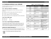
... a Service Call Error occurs and "EPSON Printer W indow!3" pops up the BIO S settings screen with Engine • Replace the Main Board. on "Apple Talk" while using EPSON LINK3. E0009 E0014 Abnormal Laser Refer to users. Turning on the screen, press Ctrl+Shift+Enter together to 3.4.2.2 of the EPL-5700 Service Manual. EPL-5700L/5700i 3.2 HANDLING SERVICE CALL ERRORS This...
... a Service Call Error occurs and "EPSON Printer W indow!3" pops up the BIO S settings screen with Engine • Replace the Main Board. on "Apple Talk" while using EPSON LINK3. E0009 E0014 Abnormal Laser Refer to users. Turning on the screen, press Ctrl+Shift+Enter together to 3.4.2.2 of the EPL-5700 Service Manual. EPL-5700L/5700i 3.2 HANDLING SERVICE CALL ERRORS This...
Service Manual
Page 31
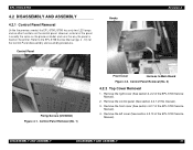
...section 4.2.2 of the EPL-5700 Service Manual). 4. DISASSEMBLY AND ASSEMBLY DISASSEMBLY AND ASSEMBLY 31 EPL-5700L/5700i 4.2 DISASSEMBLY AND ASSEMBLY 4.2.1 Control Panel Removal Unlike the previous m odel, the EPL-5700L/5700i has only two LED lam ps and no other functions on the printer. Refer to Main Board... Figure 4-2. Remove the front cover (See section 4.2.7 of the EPL-5700 Service Manual). 2. Control Panel Hooks Revision A Fixing ...
...section 4.2.2 of the EPL-5700 Service Manual). 4. DISASSEMBLY AND ASSEMBLY DISASSEMBLY AND ASSEMBLY 31 EPL-5700L/5700i 4.2 DISASSEMBLY AND ASSEMBLY 4.2.1 Control Panel Removal Unlike the previous m odel, the EPL-5700L/5700i has only two LED lam ps and no other functions on the printer. Refer to Main Board... Figure 4-2. Remove the front cover (See section 4.2.7 of the EPL-5700 Service Manual). 2. Control Panel Hooks Revision A Fixing ...
Service Manual
Page 33
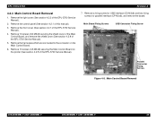
EPL-5700L/5700i Revision A 4.2.3 Main Control Board Removal 1. Remove the front cover (See section 4.2.7 of this manual). 3. Remove the control panel (See section 4.2.1 of the EPL-5700 Service Manual). 4. Main Board Fixing Screws USB Connector Fixing Screw Parallel Connector Fixing Screws Figure 4-5. Main Control Board Removal DISASSEMBLY AND ... for parallel interface (CP M3x6), and remove the board. Remove the harnesses which are connected to the connector on the printer (See section 4.2.9 of the EPL-5700 Service Manual). 5. Remove the right cover (See section 4.2.2 of the...
EPL-5700L/5700i Revision A 4.2.3 Main Control Board Removal 1. Remove the front cover (See section 4.2.7 of this manual). 3. Remove the control panel (See section 4.2.1 of the EPL-5700 Service Manual). 4. Main Board Fixing Screws USB Connector Fixing Screw Parallel Connector Fixing Screws Figure 4-5. Main Control Board Removal DISASSEMBLY AND ... for parallel interface (CP M3x6), and remove the board. Remove the harnesses which are connected to the connector on the printer (See section 4.2.9 of the EPL-5700 Service Manual). 5. Remove the right cover (See section 4.2.2 of the...
Service Manual
Page 39
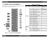
...Control Board - APPENDIX CONNECTOR PIN ASSIGNMENTS 39 Connector List Board Connector Function Reference CN1 EPL-5700 Service For Expanded RAMSIMM, 72 pin Manual, Table 7-5 and 7-7 CN2 Parallel Interface, 36 pin EPL-5700 Service Manual, Table 7-8 CN3 Video (not used) - CN5 USB Interface Table 7-2 CN202... - CN3 Interlock Switch Control - C292 MAIN CN204 High Voltage Board - Power Board CN2 Fusing Heater Lamp Control - EPL-5700L/5700i 7.1 CONNECTOR PIN ASSIGNMENTS The figure below shows interconnections with the Main Board Revision A Table 7-1. Interconnection with the M ...
...Control Board - APPENDIX CONNECTOR PIN ASSIGNMENTS 39 Connector List Board Connector Function Reference CN1 EPL-5700 Service For Expanded RAMSIMM, 72 pin Manual, Table 7-5 and 7-7 CN2 Parallel Interface, 36 pin EPL-5700 Service Manual, Table 7-8 CN3 Video (not used) - CN5 USB Interface Table 7-2 CN202... - CN3 Interlock Switch Control - C292 MAIN CN204 High Voltage Board - Power Board CN2 Fusing Heater Lamp Control - EPL-5700L/5700i 7.1 CONNECTOR PIN ASSIGNMENTS The figure below shows interconnections with the Main Board Revision A Table 7-1. Interconnection with the M ...


