Instruction Manual
Page 5
...exposed metal parts of the spinning accessory. After inspecting and installing an accessory, position yourself and bystanders away from work area must match the grinder spindle thread. Damaged accessories will run the power tool at least equal to the maximum speed marked on application, use a damaged accessory....cause loss of the power tool will normally break apart during this power tool. c) Do not use inspect the accessory such as a grinder, sander, wire brush or polisher. Before each use accessories which the power tool was not designed may fly away and cause injury ...
...exposed metal parts of the spinning accessory. After inspecting and installing an accessory, position yourself and bystanders away from work area must match the grinder spindle thread. Damaged accessories will run the power tool at least equal to the maximum speed marked on application, use a damaged accessory....cause loss of the power tool will normally break apart during this power tool. c) Do not use inspect the accessory such as a grinder, sander, wire brush or polisher. Before each use accessories which the power tool was not designed may fly away and cause injury ...

Instruction Manual
Page 9
... it may dismount from power sanding, sawing, grinding, drilling, and other construction activities. WARNING: When not in a well ventilated area, and work in use, place grinder on the skin may cause serious personal injury. If grinding wheel or accessory loosens, it will not move inadvertantly, roll or cause a tripping or falling...
... it may dismount from power sanding, sawing, grinding, drilling, and other construction activities. WARNING: When not in a well ventilated area, and work in use, place grinder on the skin may cause serious personal injury. If grinding wheel or accessory loosens, it will not move inadvertantly, roll or cause a tripping or falling...
Instruction Manual
Page 10
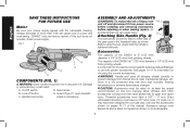
...manual. FIG. 1 C B A D E COMPONENTS (FIG. 1) WARNING: Never modify the power tool or any part of the DW831 is 7" (180 mm) diameter x 1/4" (6.35 mm) thick grinding wheels. Lock off and disconnect it from thermal shock, heat, ...to prevent damage from power source before installing and removing accessories, before adjusting or when making repairs. DeWALT tools are factory tested; Guard (Type 27, open beneath C. It is tightened secure... Be sure your power supply agrees with grinder accessories. Damage or personal injury could result. Side handle B.
...manual. FIG. 1 C B A D E COMPONENTS (FIG. 1) WARNING: Never modify the power tool or any part of the DW831 is 7" (180 mm) diameter x 1/4" (6.35 mm) thick grinding wheels. Lock off and disconnect it from thermal shock, heat, ...to prevent damage from power source before installing and removing accessories, before adjusting or when making repairs. DeWALT tools are factory tested; Guard (Type 27, open beneath C. It is tightened secure... Be sure your power supply agrees with grinder accessories. Damage or personal injury could result. Side handle B.

Instruction Manual
Page 12
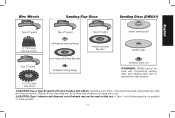
English 5" (125 mm) Grinding Wheels (DW831) Type 27 guard unthreaded backing flange Type 27 depressed center wheel threaded locking flange 7" (180 mm) Grinding Wheels (DW840) Type 27 guard backing flange Type 27 non-hubbed wheel clamp nut Type 27 guard Type 27 hubbed wheel Type 27 guard Type 27 hubbed wheel 10 CAUTION: Type 1 abrasive and diamond cut -off wheels may not be used on this tool. A Type 1 cut -off wheel guard is not available for these grinders.
English 5" (125 mm) Grinding Wheels (DW831) Type 27 guard unthreaded backing flange Type 27 depressed center wheel threaded locking flange 7" (180 mm) Grinding Wheels (DW840) Type 27 guard backing flange Type 27 non-hubbed wheel clamp nut Type 27 guard Type 27 hubbed wheel Type 27 guard Type 27 hubbed wheel 10 CAUTION: Type 1 abrasive and diamond cut -off wheels may not be used on this tool. A Type 1 cut -off wheel guard is not available for these grinders.
Instruction Manual
Page 13
CAUTION: Type 1 abrasive and diamond cut -off wheel guard is not available for these grinders. 11 Strands of wire may break and fly off wheels may not be used on this tool. Operators and others in use. A Type 1 cut -off ...when wire wheels and brushes are in the area should wear appropriate eye, face and body protection. Wire Wheels Sanding Flap Discs Sanding Discs (DW831) English Type 27 guard Type 27 guard Type 27 guard rubber backing pad 3" (76.2 mm) wire cup brush unthreaded backing flange hubbed sanding flap disc...
CAUTION: Type 1 abrasive and diamond cut -off wheel guard is not available for these grinders. 11 Strands of wire may break and fly off wheels may not be used on this tool. Operators and others in use. A Type 1 cut -off ...when wire wheels and brushes are in the area should wear appropriate eye, face and body protection. Wire Wheels Sanding Flap Discs Sanding Discs (DW831) English Type 27 guard Type 27 guard Type 27 guard rubber backing pad 3" (76.2 mm) wire cup brush unthreaded backing flange hubbed sanding flap disc...
Instruction Manual
Page 15
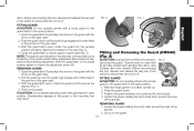
... and Removing the Guard (DW840) (Fig. 8) CAUTION: Unplug the tool before mounting or FIG. 8 removing the guard. FITTING GUARD CAUTION: Do not operate grinder with a loose guard or the guard latch in the open position. Lift up . 2. Before reconnecting the tool, depress and release the rear part of the... spindle. Position the guard between your body and the work piece. 4. FIG. 6 FIG. 7 English FITTING GUARD CAUTION: Do not operate grinder with a loose guard or the guard latch in the open position. 1. Guards must be used with the arrow on the guard with all grinding ...
... and Removing the Guard (DW840) (Fig. 8) CAUTION: Unplug the tool before mounting or FIG. 8 removing the guard. FITTING GUARD CAUTION: Do not operate grinder with a loose guard or the guard latch in the open position. Lift up . 2. Before reconnecting the tool, depress and release the rear part of the... spindle. Position the guard between your body and the work piece. 4. FIG. 6 FIG. 7 English FITTING GUARD CAUTION: Do not operate grinder with a loose guard or the guard latch in the open position. 1. Guards must be used with the arrow on the guard with all grinding ...
Instruction Manual
Page 16
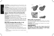
... pads are complete. Place the backing flange on the backing flange pilot.) 3. Place the wheel against the flange. (For the DW831, center the grinding wheel on the grinder spindle (Fig. 9). 2. CAUTION: Wear work gloves when handling wire cup brushes. An accidental start-up can fly apart and ...Mounting Grinding Wheels (Fig. 9-12) Grinding wheels are designed for surface grinding while thinner Type 27 wheels need to be rated for this grinder. Rotate the spindle by hand while pressing the spindle lock button (Fig. 11) until the spindle locks, preventing the spindle from power ...
... pads are complete. Place the backing flange on the backing flange pilot.) 3. Place the wheel against the flange. (For the DW831, center the grinding wheel on the grinder spindle (Fig. 9). 2. CAUTION: Wear work gloves when handling wire cup brushes. An accidental start-up can fly apart and ...Mounting Grinding Wheels (Fig. 9-12) Grinding wheels are designed for surface grinding while thinner Type 27 wheels need to be rated for this grinder. Rotate the spindle by hand while pressing the spindle lock button (Fig. 11) until the spindle locks, preventing the spindle from power ...


