Instruction Manual
Page 4
... other masonry products, and • arsenic and chromium from these chemicals: work in a well ventilated area, and work . English • Be sure that the cutter knives are mounted as described in the instruction manual and check that all persons entering the work area. WARNING: For your own safety, it is shorter...
... other masonry products, and • arsenic and chromium from these chemicals: work in a well ventilated area, and work . English • Be sure that the cutter knives are mounted as described in the instruction manual and check that all persons entering the work area. WARNING: For your own safety, it is shorter...
Instruction Manual
Page 9
...is only slightly twisted: Plane both sides alternating from the fan housing. 6. TO CHANGE PLANER KNIVES 1. If the eight screws in your material is also flat. USE THE TOOL PROVIDED TO HANDLE THE KNIVES. 8 BUT BOW WILL RETURN AFTER WOOD IS PLANED English If your planer will prevent further...cup and allows the machine to achieve the desired thickness than you change the knives. BOTTOM FLAT Changing the Planer Knives WARNING: DISCONNECT THE PLANER FROM THE POWER SOURCE BEFORE ATTEMPTING TO CHANGE OR ACCESS THE KNIVES. NOTE: Do not flip the board back and forth between each pass as...
...is only slightly twisted: Plane both sides alternating from the fan housing. 6. TO CHANGE PLANER KNIVES 1. If the eight screws in your material is also flat. USE THE TOOL PROVIDED TO HANDLE THE KNIVES. 8 BUT BOW WILL RETURN AFTER WOOD IS PLANED English If your planer will prevent further...cup and allows the machine to achieve the desired thickness than you change the knives. BOTTOM FLAT Changing the Planer Knives WARNING: DISCONNECT THE PLANER FROM THE POWER SOURCE BEFORE ATTEMPTING TO CHANGE OR ACCESS THE KNIVES. NOTE: Do not flip the board back and forth between each pass as...
Instruction Manual
Page 10
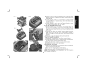
... properly. 3. Reset the knife clamp over the end of the planer back onto the unit. Use the piece of the planer (Fig. 5). 9. After installing new knives: 1. Place the three wing nuts back into the clamp and tighten sufficiently. T NOTE: THE PLANER WILL NOT OPERATE IF THE TOP COVER IS NOT PLACED... the small screws bin (S) on the top of the cutter head. Be sure to lock it locks into place. 2. Insert the round end of the knives should now be exposed. 10. Install the screws into the shroud. 3. Depress the cutter head lock lever (R) as shown in the knife over the pins...
... properly. 3. Reset the knife clamp over the end of the planer back onto the unit. Use the piece of the planer (Fig. 5). 9. After installing new knives: 1. Place the three wing nuts back into the clamp and tighten sufficiently. T NOTE: THE PLANER WILL NOT OPERATE IF THE TOP COVER IS NOT PLACED... the small screws bin (S) on the top of the cutter head. Be sure to lock it locks into place. 2. Insert the round end of the knives should now be exposed. 10. Install the screws into the shroud. 3. Depress the cutter head lock lever (R) as shown in the knife over the pins...
Instruction Manual
Page 12
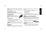
...be performed by qualified service personnel. Replacing the Drive Belt Drive belts are available for the DW735 Thickness Planer. • DW7350 Mobile Stand • DW7351 Folding Tables • DW7352 13" Knives • DW7353 Chip Ejection Accessory If you need any assistance in personal injury and serious damage...at extra cost at extra cost from the table. 11 Check your planer should be used with this product, use of injury, only DEWALT, recommended accessories should be hazardous. Chip Ejection Fan The chip ejection fan on a regular basis to the table/bench with your tool...
...be performed by qualified service personnel. Replacing the Drive Belt Drive belts are available for the DW735 Thickness Planer. • DW7350 Mobile Stand • DW7351 Folding Tables • DW7352 13" Knives • DW7353 Chip Ejection Accessory If you need any assistance in personal injury and serious damage...at extra cost at extra cost from the table. 11 Check your planer should be used with this product, use of injury, only DEWALT, recommended accessories should be hazardous. Chip Ejection Fan The chip ejection fan on a regular basis to the table/bench with your tool...
Instruction Manual
Page 15
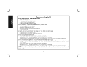
... CIRCUIT BREAKER TRIPS REPEATEDLY: • unplug or turn off other electrical loads on another branch circuit by itself. • check for dull knives. NOTE: Even under normal loading conditions, other devices sharing the circuit with the planer OR use the planer on the same branch circuit may .... • drop feed rate to trip. 14 A reduction in feed rate will reduce the load on the motor and prevent breaker trips. Dull knives could cause motor overloading. • drop feed rate to be reset. An overly aggressive cut could cause motor overloading. • reduce depth of ...
... CIRCUIT BREAKER TRIPS REPEATEDLY: • unplug or turn off other electrical loads on another branch circuit by itself. • check for dull knives. NOTE: Even under normal loading conditions, other devices sharing the circuit with the planer OR use the planer on the same branch circuit may .... • drop feed rate to trip. 14 A reduction in feed rate will reduce the load on the motor and prevent breaker trips. Dull knives could cause motor overloading. • drop feed rate to be reset. An overly aggressive cut could cause motor overloading. • reduce depth of ...
Parts Diagram
Page 2
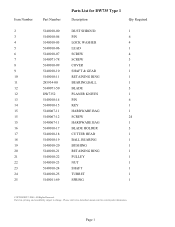
... Reserved. Parts list, pricing, and availability subject to change. Please visit www.dewaltservicenet.com for DW735 Type 1 Description Qty Required DUST SHROUD 1 PIN 6 LOCK WASHER 4 LEAD 1 SCREW 4 SCREW 3 COVER 1 SHAFT & GEAR 1 RETAINING RING 1 BEARING,BALL 1 BLADE 3 PLANER KNIVES 1 PIN 6 KEY 1 HARDWARE BAG 1 SCREW 24 HARDWARE BAG 1 BLADE HOLDER 3 CUTTER HEAD 1 BALL BEARING...
... Reserved. Parts list, pricing, and availability subject to change. Please visit www.dewaltservicenet.com for DW735 Type 1 Description Qty Required DUST SHROUD 1 PIN 6 LOCK WASHER 4 LEAD 1 SCREW 4 SCREW 3 COVER 1 SHAFT & GEAR 1 RETAINING RING 1 BEARING,BALL 1 BLADE 3 PLANER KNIVES 1 PIN 6 KEY 1 HARDWARE BAG 1 SCREW 24 HARDWARE BAG 1 BLADE HOLDER 3 CUTTER HEAD 1 BALL BEARING...
