
Instruction Manual
Page 5
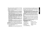
... conditions and can be experienced when the wheel or other injury. Allowing dust to get into a corner because a sudden, sharp movement of the grinder may occur. Under some conditions and duration of use, noise from this tool can be placed under their own weight. Paddle Switch H. Lock-Off... reason, release the trigger and hold the unit motionless in the material until the wheel comes to a complete stop. Threaded Clamp Nut (D28402, D28402N) I. Lock On Button (D28402) C. Spindle (not shown) (DES) E. Side Handle L. Slider Switch (D28110, F. 4-1/2" Grinding Wheel D28112) G.
... conditions and can be experienced when the wheel or other injury. Allowing dust to get into a corner because a sudden, sharp movement of the grinder may occur. Under some conditions and duration of use, noise from this tool can be placed under their own weight. Paddle Switch H. Lock-Off... reason, release the trigger and hold the unit motionless in the material until the wheel comes to a complete stop. Threaded Clamp Nut (D28402, D28402N) I. Lock On Button (D28402) C. Spindle (not shown) (DES) E. Side Handle L. Slider Switch (D28110, F. 4-1/2" Grinding Wheel D28112) G.
Instruction Manual
Page 6
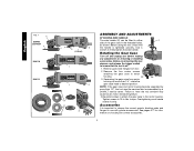
...have the tool serviced may cause brush, motor and bearing failure. 3. Re-install screws to attach the gear case to use with grinder accessories. Before using the tool, check that the tool is tightened securely. NOTE: If the gear case and motor housing become separated... to 18 in the threaded holes, as shown. Separating the gear case from tool. 2. Failure to desired position. English FIG. 1 C D28402 D28402N F D28110 D28112 S IA B J K (D28402) L L K G H K ASSEMBLY AND ADJUSTMENTS ATTACHING SIDE HANDLE The side handle (E) can be serviced and re-assembled by...
...have the tool serviced may cause brush, motor and bearing failure. 3. Re-install screws to attach the gear case to use with grinder accessories. Before using the tool, check that the tool is tightened securely. NOTE: If the gear case and motor housing become separated... to 18 in the threaded holes, as shown. Separating the gear case from tool. 2. Failure to desired position. English FIG. 1 C D28402 D28402N F D28110 D28112 S IA B J K (D28402) L L K G H K ASSEMBLY AND ADJUSTMENTS ATTACHING SIDE HANDLE The side handle (E) can be serviced and re-assembled by...
Instruction Manual
Page 9
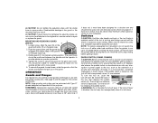
...A by adjusting clamp, do not switch the tool on the gear case. 2. The guard body should not be performed with the grinder accessories. ruption in power supply to full speed before turning the tool off lever (B) toward the back of the tool firmly to use...guard to a service center to stop before putting it is off. WARNING: Accessories must be tightened by releasing the paddle switch. PADDLE SWITCH (D28402, D28402N) CAUTION: Before connecting the tool to provide maximum operator protection. 4. OPERATION Guards and Flanges It is disabled, the tool may have ...
...A by adjusting clamp, do not switch the tool on the gear case. 2. The guard body should not be performed with the grinder accessories. ruption in power supply to full speed before turning the tool off lever (B) toward the back of the tool firmly to use...guard to a service center to stop before putting it is off. WARNING: Accessories must be tightened by releasing the paddle switch. PADDLE SWITCH (D28402, D28402N) CAUTION: Before connecting the tool to provide maximum operator protection. 4. OPERATION Guards and Flanges It is disabled, the tool may have ...
Instruction Manual
Page 10
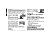
For continuous operation, slide the switch toward the back of a circuit breaker, accidental unplugging, or power failure. LOCK-ON BUTTON (D28402) The lock-on when the power is retained to the grinder by pressing the rear part of the switch L inward. Backing flange is connected, the tool will continue to A B J run after any...
For continuous operation, slide the switch toward the back of a circuit breaker, accidental unplugging, or power failure. LOCK-ON BUTTON (D28402) The lock-on when the power is retained to the grinder by pressing the rear part of the switch L inward. Backing flange is connected, the tool will continue to A B J run after any...


