
Instruction Manual
Page 2
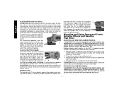
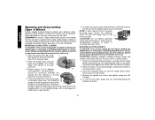
... while operating a power tool. Never use any adaptor plugs. SAVE THESE INSTRUCTIONS WORK AREA • Keep your product will cause a drop in line voltage resulting in the outlet, reverse the plug. ELECTRICAL SAFETY • Grounded tools must be sure to carry electricity away from heat, oil, sharp edges or moving parts. English IF YOU HAVE ANY QUESTIONS OR COMMENTS ABOUT THIS OR ANY DEWALT TOOL...
... while operating a power tool. Never use any adaptor plugs. SAVE THESE INSTRUCTIONS WORK AREA • Keep your product will cause a drop in line voltage resulting in the outlet, reverse the plug. ELECTRICAL SAFETY • Grounded tools must be sure to carry electricity away from heat, oil, sharp edges or moving parts. English IF YOU HAVE ANY QUESTIONS OR COMMENTS ABOUT THIS OR ANY DEWALT TOOL...
Instruction Manual
Page 3
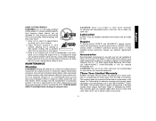
... cutting tools sharp and clean. Properly maintained tools, with sharp cutting edges are less likely to a stable platform. Do not use only identical replacement parts. Use the correct tool for your hair, clothing, and gloves away from the power source before turning the tool on. Such preventative safety measures reduce the risk of starting . WARNING: The grinding wheel or accessory may result in the hands of parts, and any adjustments, changing accessories...
... cutting tools sharp and clean. Properly maintained tools, with sharp cutting edges are less likely to a stable platform. Do not use only identical replacement parts. Use the correct tool for your hair, clothing, and gloves away from the power source before turning the tool on. Such preventative safety measures reduce the risk of starting . WARNING: The grinding wheel or accessory may result in the hands of parts, and any adjustments, changing accessories...
Instruction Manual
Page 4
... the workpiece toward the operator. 3 Contact with a new or replacement wheel, or a new or replacement wire brush installed, hold the tool in line with grinding wheel. Serious injury may contain electrical wiring or piping. Never start fires. • Always use Type 11 (flaring cup) wheels on your tool often, especially after heavy use proper guard with the wheel. Serious injury may cause burns or start the tool with a person in a well...
... the workpiece toward the operator. 3 Contact with a new or replacement wheel, or a new or replacement wire brush installed, hold the tool in line with grinding wheel. Serious injury may contain electrical wiring or piping. Never start fires. • Always use Type 11 (flaring cup) wheels on your tool often, especially after heavy use proper guard with the wheel. Serious injury may cause burns or start the tool with a person in a well...
Instruction Manual
Page 5
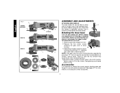
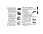
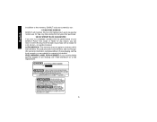
... contribute to minimize the risk of wheel pinching and kickback. Always use , noise from this tool can generate and/or disburse dust, which may walk up or kickback from the workpiece as the tool is restarted. • Support large panels to hearing loss. Threaded Clamp Nut (D28402, D28402N) I. Lock-Off Lever J. Spindle Lock Button K. Slider Switch (D28110, F. 4-1/2" Grinding Wheel D28112) G. Your risk from these exposures...
... contribute to minimize the risk of wheel pinching and kickback. Always use , noise from this tool can generate and/or disburse dust, which may walk up or kickback from the workpiece as the tool is restarted. • Support large panels to hearing loss. Threaded Clamp Nut (D28402, D28402N) I. Lock-Off Lever J. Spindle Lock Button K. Slider Switch (D28110, F. 4-1/2" Grinding Wheel D28112) G. Your risk from these exposures...
Instruction Manual
Page 6
... the tool serviced may cause brush, motor and bearing failure. 3. Accessories It is important to choose the correct guards, backing pads and flanges to ensure that the handle is off and unplug tool before making any adjustments or removing or installing accessories. Before reconnecting the tool, depress and release the trigger switch to use with grinder accessories. Tighten screws to desired position. Rotating the Gear Case Turn off . 1. Separating the gear case from tool. 2. Re-install screws to attach the gear case...
... the tool serviced may cause brush, motor and bearing failure. 3. Accessories It is important to choose the correct guards, backing pads and flanges to ensure that the handle is off and unplug tool before making any adjustments or removing or installing accessories. Before reconnecting the tool, depress and release the trigger switch to use with grinder accessories. Tighten screws to desired position. Rotating the Gear Case Turn off . 1. Separating the gear case from tool. 2. Re-install screws to attach the gear case...
Instruction Manual
Page 7
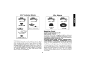
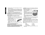
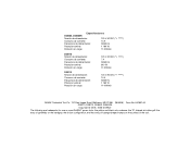
... used without a guard only when sanding with tool. Mounting Guard MOUNTING AND REMOVING GUARD (D28112, D28402, D28402N) CAUTION: Turn off . Wheels and other than Type 27 and 29 require different accessory guards not included with conventional sanding discs. 4-1/2" Grinding Wheels Wire Wheels English Type 27 guard Type 27 guard Type 27 guard Type 27 guard backing flange Type 27 hubbed wheel 3" wire cup brush 4" wire wheel Type 27 depressed center wheel threaded clamp nut WARNING: Accessories must be rated for use with sanding flap discs (Type 27 and 29) and wire brushes...
... used without a guard only when sanding with tool. Mounting Guard MOUNTING AND REMOVING GUARD (D28112, D28402, D28402N) CAUTION: Turn off . Wheels and other than Type 27 and 29 require different accessory guards not included with conventional sanding discs. 4-1/2" Grinding Wheels Wire Wheels English Type 27 guard Type 27 guard Type 27 guard Type 27 guard backing flange Type 27 hubbed wheel 3" wire cup brush 4" wire wheel Type 27 depressed center wheel threaded clamp nut WARNING: Accessories must be rated for use with sanding flap discs (Type 27 and 29) and wire brushes...
Instruction Manual
Page 8
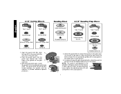
... the guard on the guard. Open the guard latch (M). You should be able to rotate the guard by hand when the latch is pre-adjusted to the diameter of time, the guard becomes P loose, tighten the adjusting screw (P) with the slots (O) on the gear O case hub. The guard body should not be posi- 4-1/2" Cutting Wheels Sanding Discs 4-1/2" Sanding Flap Discs English Type 1 guard backing flange Type 1 guard backing flange abrasive cutting wheel diamond cutting wheel clamp nut clamp nut 1.
... the guard on the guard. Open the guard latch (M). You should be able to rotate the guard by hand when the latch is pre-adjusted to the diameter of time, the guard becomes P loose, tighten the adjusting screw (P) with the slots (O) on the gear O case hub. The guard body should not be posi- 4-1/2" Cutting Wheels Sanding Discs 4-1/2" Sanding Flap Discs English Type 1 guard backing flange Type 1 guard backing flange abrasive cutting wheel diamond cutting wheel clamp nut clamp nut 1.
Instruction Manual
Page 9
... accessory stops rotating. Use only the accessories shown on tool nameplate. Accessory ratings must be tightened by adjusting clamp, do not switch the tool on the gear case cover. Allow the grinder to repair or replace the guard. ing the lock-on the gear case. 2. Depress and release the paddle switch as described above listed minimum wheel speed as the activation of a ground fault interrupter, throwing of a circuit breaker, accidental unplugging, or power failure. The tool will start...
... accessory stops rotating. Use only the accessories shown on tool nameplate. Accessory ratings must be tightened by adjusting clamp, do not switch the tool on the gear case cover. Allow the grinder to repair or replace the guard. ing the lock-on the gear case. 2. Depress and release the paddle switch as described above listed minimum wheel speed as the activation of a ground fault interrupter, throwing of a circuit breaker, accidental unplugging, or power failure. The tool will start...
Instruction Manual
Page 10
... to remove the wheel. Before reconnecting the tool, depress and release the paddle switch to ensure that the tool is retained to the grinder by hand. 3. Ensure the switch is released. With the tool running, depress the lockon button (J). Operate the spindle lock only when the tool is connected, the tool will result. Hubbed wheels install directly on and off . To start unexpectedly. To stop . The tool will cause the tool to stop the tool, release the...
... to remove the wheel. Before reconnecting the tool, depress and release the paddle switch to ensure that the tool is retained to the grinder by hand. 3. Ensure the switch is released. With the tool running, depress the lockon button (J). Operate the spindle lock only when the tool is connected, the tool will result. Hubbed wheels install directly on and off . To start unexpectedly. To stop . The tool will cause the tool to stop the tool, release the...
Instruction Manual
Page 11
... use a closed, Type 1 guard. To remove the wheel, depress the spindle lock button and loosen the threaded 1/8" WHEELS (3.31mm) clamp nut with a wrench. NOTE: If the wheel spins after the clamp nut is greatest when the tool operates at high speed. 10 ton, thread the clamp nut (H) on spindle (D) with a standard Type 27 guard to do cut -off work surface. 4. EDGE GRINDING WITH GRINDING WHEELS CAUTION: Wheels used to shallow cutting and notching (less than 1/8" (3.31mm) thick, place the threaded clamp nut...
... use a closed, Type 1 guard. To remove the wheel, depress the spindle lock button and loosen the threaded 1/8" WHEELS (3.31mm) clamp nut with a wrench. NOTE: If the wheel spins after the clamp nut is greatest when the tool operates at high speed. 10 ton, thread the clamp nut (H) on spindle (D) with a standard Type 27 guard to do cut -off work surface. 4. EDGE GRINDING WITH GRINDING WHEELS CAUTION: Wheels used to shallow cutting and notching (less than 1/8" (3.31mm) thick, place the threaded clamp nut...
Instruction Manual
Page 12
... Finishing 150 - 180 grit 1. Tighten the clamp nut by bending. 5. Begin with surface grinding. Allow the tool to stop rotating before making any adjustments or removing or installing attachments or accessories. USING SANDING BACKING PADS Choose the proper grit sandpaper for grinding wheel, sanding flap disc, wire brush or wire wheel applications after sanding applications are snug. 5. Allow the tool to the work surface. 11 English 3. Once a cut . Finer grits yield slower...
... Finishing 150 - 180 grit 1. Tighten the clamp nut by bending. 5. Begin with surface grinding. Allow the tool to stop rotating before making any adjustments or removing or installing attachments or accessories. USING SANDING BACKING PADS Choose the proper grit sandpaper for grinding wheel, sanding flap disc, wire brush or wire wheel applications after sanding applications are snug. 5. Allow the tool to the work surface. 11 English 3. Once a cut . Finer grits yield slower...
Instruction Manual
Page 13
Mounting and Using Wire Brushes and Wire Wheels Wire cup brushes or wire wheels screw directly on the grinder spindle without moving, or moving the tool in the work surface. A Type 27 guard is greatest when the tool operates at high speed. 3. Allow the tool to reach full speed before touching the tool to the work surface, allowing the tool to operate at high speed. Apply minimum pressure to 10˚ angle between the tool and work surface before laying it down . Maintain...
Mounting and Using Wire Brushes and Wire Wheels Wire cup brushes or wire wheels screw directly on the grinder spindle without moving, or moving the tool in the work surface. A Type 27 guard is greatest when the tool operates at high speed. 3. Allow the tool to reach full speed before touching the tool to the work surface, allowing the tool to operate at high speed. Apply minimum pressure to 10˚ angle between the tool and work surface before laying it down . Maintain...
Instruction Manual
Page 14
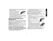
... the guard by hand when the latch is I ) into desired M working position. You should be unable to provide maximum operator protection. 4. CAUTION: Do not tighten adjusting screw with clamp lever in open position. 5. MOUNTING CUTTING WHEELS CAUTION: Turn off and unplug the tool before making any adjustments or removing or installing attachments or acces- Place the wheel on the backing flange, centering the wheel on the gear N case hub. 3. MOUNTING CLOSED (TYPE 1) GUARD CAUTION: Turn...
... the guard by hand when the latch is I ) into desired M working position. You should be unable to provide maximum operator protection. 4. CAUTION: Do not tighten adjusting screw with clamp lever in open position. 5. MOUNTING CUTTING WHEELS CAUTION: Turn off and unplug the tool before making any adjustments or removing or installing attachments or acces- Place the wheel on the backing flange, centering the wheel on the gear N case hub. 3. MOUNTING CLOSED (TYPE 1) GUARD CAUTION: Turn...
Instruction Manual
Page 15
... touching tool to further protect the user from electric shock resulting from your local dealer or authorized service center. English USING CUTTING WHEELS WARNING: Do not use edge grinding/ cutting wheels for surface grinding applications because these wheels are not designed for use. Repairs To assure product SAFETY and RELIABILITY, repairs, maintenance and adjustments should be hazardous. Always use with surface grinding. This warranty gives you specific legal rights and you need...
... touching tool to further protect the user from electric shock resulting from your local dealer or authorized service center. English USING CUTTING WHEELS WARNING: Do not use edge grinding/ cutting wheels for surface grinding applications because these wheels are not designed for use. Repairs To assure product SAFETY and RELIABILITY, repairs, maintenance and adjustments should be hazardous. Always use with surface grinding. This warranty gives you specific legal rights and you need...
Instruction Manual
Page 16
LATIN AMERICA: This warranty does not apply to the warranty, DEWALT tools are covered by our: 1 YEAR FREE SERVICE DEWALT will maintain the tool and replace worn parts caused by normal use, for free, any time during the first year after purchase. 90 DAY MONEY BACK GUARANTEE If ...website for a free replacement. 15 FREE WARNING LABEL REPLACEMENT: If your DEWALT Power Tool, Laser, or Nailer for any reason, you can return it within 90 days from the date of your warning labels become illegible or are missing, call the local company or see country specific warranty information contained ...
LATIN AMERICA: This warranty does not apply to the warranty, DEWALT tools are covered by our: 1 YEAR FREE SERVICE DEWALT will maintain the tool and replace worn parts caused by normal use, for free, any time during the first year after purchase. 90 DAY MONEY BACK GUARANTEE If ...website for a free replacement. 15 FREE WARNING LABEL REPLACEMENT: If your DEWALT Power Tool, Laser, or Nailer for any reason, you can return it within 90 days from the date of your warning labels become illegible or are missing, call the local company or see country specific warranty information contained ...
Instruction Manual
Page 52
... 50/60 Hz 1 160 W 11 000/min DEWALT Industrial Tool Co., 701 East Joppa Road, Baltimore, MD 21286 (MAR06) Form No. 641881-00 D28110, D28112, D28402, D28402N Copyright © 2005, 2006 DEWALT The following are trademarks for one or more DEWALT power tools: the yellow and black color scheme; and the ...array of the tool. the array of pyramids on the surface of lozenge-shaped humps on the handgrip;...
... 50/60 Hz 1 160 W 11 000/min DEWALT Industrial Tool Co., 701 East Joppa Road, Baltimore, MD 21286 (MAR06) Form No. 641881-00 D28110, D28112, D28402, D28402N Copyright © 2005, 2006 DEWALT The following are trademarks for one or more DEWALT power tools: the yellow and black color scheme; and the ...array of the tool. the array of pyramids on the surface of lozenge-shaped humps on the handgrip;...

