
Instruction Manual
Page 5
... and cause injury beyond immediate area of the power tool is intended to the maximum speed marked on application, use inspect the accessory such as a grinder, sander, wire brush, polisher or cut-off tool. Accessories with this test time. g) Wear personal protective equipment. Fragments of workpiece or of the power tool...
... and cause injury beyond immediate area of the power tool is intended to the maximum speed marked on application, use inspect the accessory such as a grinder, sander, wire brush, polisher or cut-off tool. Accessories with this test time. g) Wear personal protective equipment. Fragments of workpiece or of the power tool...

Instruction Manual
Page 8
... another practical way to secure and support the workpiece to a stable platform. The smaller the gauge number, the heavier the cord. Additional Safety Rules for Grinders WARNING: The grinding wheel or accessory may loosen during ordinary operation. If grinding wheel or accessory loosens, it rough treatment. If this occurs, stop the...
... another practical way to secure and support the workpiece to a stable platform. The smaller the gauge number, the heavier the cord. Additional Safety Rules for Grinders WARNING: The grinding wheel or accessory may loosen during ordinary operation. If grinding wheel or accessory loosens, it rough treatment. If this occurs, stop the...

Instruction Manual
Page 10
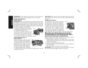
...Type 27 Guard (not shown) I2. Slider Switch: D28131, D28140 D28144, D28144N G1.Quick-Change Backing Flange INTENDED USE The D28114, D28114N, D28131, D28140, D28144, D28144N heavyduty angle grinders have been designed for professional grinding at various work sites (i.e., ... D28144 F1. 6" (152 mm) Grinding Wheel K. These heavy-duty angle grinders are professional power tools. Spindle Lock Button D28140, D28144, D28144N D. Anti-Vibration Side Handle I1. A. English FIG. 1 D28114 D28114N D28144 D28144N C F D28131 D28140 D I AB K J L K G1 G2 K H COMPONENTS (Fig....
...Type 27 Guard (not shown) I2. Slider Switch: D28131, D28140 D28144, D28144N G1.Quick-Change Backing Flange INTENDED USE The D28114, D28114N, D28131, D28140, D28144, D28144N heavyduty angle grinders have been designed for professional grinding at various work sites (i.e., ... D28144 F1. 6" (152 mm) Grinding Wheel K. These heavy-duty angle grinders are professional power tools. Spindle Lock Button D28140, D28144, D28144N D. Anti-Vibration Side Handle I1. A. English FIG. 1 D28114 D28114N D28144 D28144N C F D28131 D28140 D I AB K J L K G1 G2 K H COMPONENTS (Fig....

Instruction Manual
Page 12
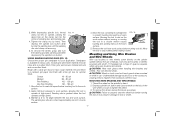
... depressed center wheel threaded clamp nut threaded clamp nut Accessories It is important to choose the correct guards, backing pads and flanges to use with grinder accessories. Use only the accessories shown on choosing the correct accessories. See pages 10-12 for at least the speed recommended on tool nameplate. 10...
... depressed center wheel threaded clamp nut threaded clamp nut Accessories It is important to choose the correct guards, backing pads and flanges to use with grinder accessories. Use only the accessories shown on choosing the correct accessories. See pages 10-12 for at least the speed recommended on tool nameplate. 10...

Instruction Manual
Page 14
...maximum operator protection. 4. NOTE: The guard is closed position. 12 Mounting instructions for use with the slots (O) on the gear case. Some DEWALT models are provided with a guard intended for use with a loose guard or the clamp lever in the accessory package. 1. Close the guard ...case. The same guard is designed for these accessory guards are aligned and pull up on the gear case hub. 3. Do not operate the grinder with sanding flap discs O I ) into the desired working position. The guard body should not be used with conventional sanding discs. Open ...
...maximum operator protection. 4. NOTE: The guard is closed position. 12 Mounting instructions for use with the slots (O) on the gear case. Some DEWALT models are provided with a guard intended for use with a loose guard or the clamp lever in the accessory package. 1. Close the guard ...case. The same guard is designed for these accessory guards are aligned and pull up on the gear case hub. 3. Do not operate the grinder with sanding flap discs O I ) into the desired working position. The guard body should not be used with conventional sanding discs. Open ...

Instruction Manual
Page 15
... putting it from the surface before laying the tool down . WARNING: Accessories must have been designed for this purpose. Allow the grinder to stop before turning the tool off while under load conditions. Lift the tool from power source before installing and removing accessories,...a circuit breaker, accidental unplugging, or power failure. An accidental start feature allows a slow speed build-up and during use with the grinder accessories. Turn the tool off . This feature is important to choose the correct guards and flanges to the tool, such as shown on...
... putting it from the surface before laying the tool down . WARNING: Accessories must have been designed for this purpose. Allow the grinder to stop before turning the tool off while under load conditions. Lift the tool from power source before installing and removing accessories,...a circuit breaker, accidental unplugging, or power failure. An accidental start feature allows a slow speed build-up and during use with the grinder accessories. Turn the tool off . This feature is important to choose the correct guards and flanges to the tool, such as shown on...
Instruction Manual
Page 16
...to the work surface before turning the tool on the spindle. CAUTION: Allow the tool to reach full speed before touching tool to the grinder by pressing the rear part of a circuit breaker, accidental unplugging, or power failure. Backing flange is laid down. CAUTION: Failure to ... applications. English WARNING: Do not disable the lock-off lever (B) toward the back of the switch and release. SLIDER SWITCH (FIG. 6) D28131, D28140 CAUTION: Before connecting the tool to stop . To stop L the tool while operating in the off . To unlock the tool, depress and release...
...to the work surface before turning the tool on the spindle. CAUTION: Allow the tool to reach full speed before touching tool to the grinder by pressing the rear part of a circuit breaker, accidental unplugging, or power failure. Backing flange is laid down. CAUTION: Failure to ... applications. English WARNING: Do not disable the lock-off lever (B) toward the back of the switch and release. SLIDER SWITCH (FIG. 6) D28131, D28140 CAUTION: Before connecting the tool to stop . To stop L the tool while operating in the off . To unlock the tool, depress and release...
Instruction Manual
Page 19
... become sharp. Depress spindle lock button and use a wrench on may result in a circular motion causes 5˚-15˚ burning and swirling marks on the grinder spindle without moving, or moving the tool in damage to a medium grit paper and finish with a fine grit disc for your application. Apply minimum pressure...
... become sharp. Depress spindle lock button and use a wrench on may result in a circular motion causes 5˚-15˚ burning and swirling marks on the grinder spindle without moving, or moving the tool in damage to a medium grit paper and finish with a fine grit disc for your application. Apply minimum pressure...

Instruction Manual
Page 20
...730; to stop rotating before turning the tool off. Allow the tool to 10˚ angle between the edge of grinder may be experienced. NOTE: All grinders that use Type 1 wheels use proper flange and guard can result in a circular motion causes burning and swirling marks on... the work surface. MOUNTING CLOSED (TYPE 1) GUARD (FIG. 18, 19) 1. Push the guard down . WARNING: A closed, 2-sided cutting wheel guard is not included with this tool (D28140...
...730; to stop rotating before turning the tool off. Allow the tool to 10˚ angle between the edge of grinder may be experienced. NOTE: All grinders that use Type 1 wheels use proper flange and guard can result in a circular motion causes burning and swirling marks on... the work surface. MOUNTING CLOSED (TYPE 1) GUARD (FIG. 18, 19) 1. Push the guard down . WARNING: A closed, 2-sided cutting wheel guard is not included with this tool (D28140...

Instruction Manual
Page 21
..., rotate the guard so that the tool is possible, tighten the adjusting screw (P) with surface grinding. Cutting rate is in open position. 5. Do not operate grinder with a loose guard or clamp lever in the workpiece, do not change backing flange, centering the wheel on the guard. P CAUTION: Do not tighten adjusting...
..., rotate the guard so that the tool is possible, tighten the adjusting screw (P) with surface grinding. Cutting rate is in open position. 5. Do not operate grinder with a loose guard or clamp lever in the workpiece, do not change backing flange, centering the wheel on the guard. P CAUTION: Do not tighten adjusting...


