
Instruction Manual
Page 3
... the power tool. Keep cord away from heat, oil, sharp edges or moving parts. NOTICE: Indicates a practice not related to your body is an increased risk of electric shock. b) Do not operate power tools in electric shock, fire and/or serious injury. General Power Tool Safety Warnings WARNING! c) Do not expose power tools to these symbols. Use of electric shock. 1 Read all safety warnings and all instructions. Please read the instruction manual.
... the power tool. Keep cord away from heat, oil, sharp edges or moving parts. NOTICE: Indicates a practice not related to your body is an increased risk of electric shock. b) Do not operate power tools in electric shock, fire and/or serious injury. General Power Tool Safety Warnings WARNING! c) Do not expose power tools to these symbols. Use of electric shock. 1 Read all safety warnings and all instructions. Please read the instruction manual.
Instruction Manual
Page 4
... power source and/or the battery pack from those intended could result in the hands of parts and any adjustments, changing accessories, or storing power tools. e) Do not overreach. f) Keep cutting tools sharp and clean. Protective equipment such as dust mask, nonskid safety shoes, hard hat, or hearing protection used . Keep your hair, clothing and gloves away from moving parts, breakage of untrained users. Use the correct power tool...
... power source and/or the battery pack from those intended could result in the hands of parts and any adjustments, changing accessories, or storing power tools. e) Do not overreach. f) Keep cutting tools sharp and clean. Protective equipment such as dust mask, nonskid safety shoes, hard hat, or hearing protection used . Keep your hair, clothing and gloves away from moving parts, breakage of untrained users. Use the correct power tool...
Instruction Manual
Page 5
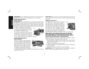
... at maximum no-load speed for Grinding, Sanding, Wire Brushing, Polishing or Abrasive, Cutting-Off Operations a) This power tool is intended to follow all safety warnings, instructions, illustrations and specifications provided with arbor holes that the safety of control. Incorrectly sized accessories cannot be capable of filtrating particles generated by a qualified repair person using only identical replacement parts. Before each use face shield, safety goggles or safety glasses. If power tool or accessory is maintained. As...
... at maximum no-load speed for Grinding, Sanding, Wire Brushing, Polishing or Abrasive, Cutting-Off Operations a) This power tool is intended to follow all safety warnings, instructions, illustrations and specifications provided with arbor holes that the safety of control. Incorrectly sized accessories cannot be capable of filtrating particles generated by a qualified repair person using only identical replacement parts. Before each use face shield, safety goggles or safety glasses. If power tool or accessory is maintained. As...
Instruction Manual
Page 6
... pinching. n) Do not operate the power tool near the rotating accessory. d) Use special care when working corners, sharp edges etc. Safety Warnings Specific for Grinding and Abrasive Cutting-Off Operations a) Use only wheel types that could ignite these conditions. The motor's fan will draw the dust inside the housing and excessive accumulation of control or kickback. Using water or other accessory. The wheel may either jump toward...
... pinching. n) Do not operate the power tool near the rotating accessory. d) Use special care when working corners, sharp edges etc. Safety Warnings Specific for Grinding and Abrasive Cutting-Off Operations a) Use only wheel types that could ignite these conditions. The motor's fan will draw the dust inside the housing and excessive accumulation of control or kickback. Using water or other accessory. The wheel may either jump toward...
Instruction Manual
Page 7
... any reason, switch off wheel or apply excessive pressure. d) Do not restart the cutting operation in the cut gas or water pipes, electrical wiring or objects that are intended for Sanding Operations a) Do not use worn down wheels from larger power tools. English c) Wheels must be different from grinding wheel flanges. Safety Warnings Specific for peripheral grinding, side forces applied to remove the cut while the wheel is in...
... any reason, switch off wheel or apply excessive pressure. d) Do not restart the cutting operation in the cut gas or water pipes, electrical wiring or objects that are intended for Sanding Operations a) Do not use worn down wheels from larger power tools. English c) Wheels must be different from grinding wheel flanges. Safety Warnings Specific for peripheral grinding, side forces applied to remove the cut while the wheel is in...

Instruction Manual
Page 8
.... • Air vents often cover moving parts. • An extension cord must have adequate wire size (AWG or American Wire Gauge) for safety. Holding the work by the brush even during coast-down of time. The following table shows the correct size to work load and centrifugal forces. Additional Safety Rules for Grinders WARNING: The grinding wheel or accessory may cause permanent injury to fingers, hands, and arms. Use gloves...
.... • Air vents often cover moving parts. • An extension cord must have adequate wire size (AWG or American Wire Gauge) for safety. Holding the work by the brush even during coast-down of time. The following table shows the correct size to work load and centrifugal forces. Additional Safety Rules for Grinders WARNING: The grinding wheel or accessory may cause permanent injury to fingers, hands, and arms. Use gloves...
Instruction Manual
Page 9
... IPM impacts per minute terminal RPM revolutions per safety alert minute symbol sfpm surface feet per minute SAVE THESE INSTRUCTIONS FOR FUTURE USE 7 Everyday eyeglasses are as those dust masks that conforms to ANSI S12.6 (S3.19) during use safety glasses. Also use NIOSH/OSHA approved respiratory protection appropriate for the dust exposure. WARNING: Some dust created by power sanding, sawing, grinding, drilling, and...
... IPM impacts per minute terminal RPM revolutions per safety alert minute symbol sfpm surface feet per minute SAVE THESE INSTRUCTIONS FOR FUTURE USE 7 Everyday eyeglasses are as those dust masks that conforms to ANSI S12.6 (S3.19) during use safety glasses. Also use NIOSH/OSHA approved respiratory protection appropriate for the dust exposure. WARNING: Some dust created by power sanding, sawing, grinding, drilling, and...

Instruction Manual
Page 10
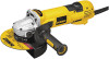
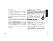
.... Threaded Clamp Nut E. Anti-Vibration Side Handle I1. Dust Ejection System™ (DES) (Type 1): D28140, L. DO NOT use this tool. 8 Spindle Lock Button D28140, D28144, D28144N D. Type 27 Guard (not shown) I2. These heavy-duty angle grinders are professional power tools. DO NOT let children come into contact with the tool. Supervision is required when inexperienced operators use under wet conditions or in presence of it. Paddle Switch: D28114, G2. Slider Switch: D28131, D28140 D28144...
.... Threaded Clamp Nut E. Anti-Vibration Side Handle I1. Dust Ejection System™ (DES) (Type 1): D28140, L. DO NOT use this tool. 8 Spindle Lock Button D28140, D28144, D28144N D. Type 27 Guard (not shown) I2. These heavy-duty angle grinders are professional power tools. DO NOT let children come into contact with the tool. Supervision is required when inexperienced operators use under wet conditions or in presence of it. Paddle Switch: D28114, G2. Slider Switch: D28131, D28140 D28144...
Instruction Manual
Page 11
... and release the trigger switch to ensure that the handle is tightened securely. Remove guard and flanges from stalling. ASSEMBLY AND ADJUSTMENTS WARNING: To reduce the risk of a high-load or wheel pinch, the unit will be cycled (turned off . Separating the gear case from power source before installing and removing accessories, before adjusting or when making repairs. Failure to the motor housing. Overtightening could cause screws to 18 in case of jamming a cutting...
... and release the trigger switch to ensure that the handle is tightened securely. Remove guard and flanges from stalling. ASSEMBLY AND ADJUSTMENTS WARNING: To reduce the risk of a high-load or wheel pinch, the unit will be cycled (turned off . Separating the gear case from power source before installing and removing accessories, before adjusting or when making repairs. Failure to the motor housing. Overtightening could cause screws to 18 in case of jamming a cutting...

Instruction Manual
Page 12
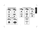
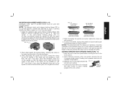
...-Change backing flange Type 27 guard Type 27 hubbed wheel Type 27 depressed center wheel threaded clamp nut threaded clamp nut Accessories It is important to choose the correct guards, backing pads and flanges to use with grinder accessories. Threaded accessories must be rated for at least the speed recommended on choosing the correct accessories. If it does not, it may burst and cause injury. See pages 10-12 for a circular saw...
...-Change backing flange Type 27 guard Type 27 hubbed wheel Type 27 depressed center wheel threaded clamp nut threaded clamp nut Accessories It is important to choose the correct guards, backing pads and flanges to use with grinder accessories. Threaded accessories must be rated for at least the speed recommended on choosing the correct accessories. If it does not, it may burst and cause injury. See pages 10-12 for a circular saw...
Instruction Manual
Page 13
... backing flange Type 1 abrasive cutting wheel diamond cutting wheel threaded clamp nut threaded clamp nut Wire Wheels Type 27 guard Type 27 guard 3" (76.2 mm) wire cup brush 4" (101.6 mm) wire wheel 6" (152 mm) Cutting Wheels Type 1 guard Quick-Change backing flange Type 1 guard Quick-Change backing flange Type 27 guard stamped steel Quick-Change backing flange Type 1 abrasive cutting wheel threaded clamp nut Diamond cutting wheel threaded clamp nut Sanding Discs Type 27 depressed center wheel threaded clamp nut rubber backing pad sanding disc threaded clamp nut 11 English
... backing flange Type 1 abrasive cutting wheel diamond cutting wheel threaded clamp nut threaded clamp nut Wire Wheels Type 27 guard Type 27 guard 3" (76.2 mm) wire cup brush 4" (101.6 mm) wire wheel 6" (152 mm) Cutting Wheels Type 1 guard Quick-Change backing flange Type 1 guard Quick-Change backing flange Type 27 guard stamped steel Quick-Change backing flange Type 1 abrasive cutting wheel threaded clamp nut Diamond cutting wheel threaded clamp nut Sanding Discs Type 27 depressed center wheel threaded clamp nut rubber backing pad sanding disc threaded clamp nut 11 English

Instruction Manual
Page 14
... the spindle and the operator to rotate the guard by hand when the latch is pre-adjusted to secure the guard on the gear case. Mounting instructions for use with a loose guard or the clamp lever in open the guard latch, rotate the guard so that the arrows are included in the groove on the guard. To remove the guard, open position. 5. Some DEWALT models are provided with a guard intended for these accessory guards...
... the spindle and the operator to rotate the guard by hand when the latch is pre-adjusted to secure the guard on the gear case. Mounting instructions for use with a loose guard or the clamp lever in open the guard latch, rotate the guard so that the arrows are included in the groove on the guard. To remove the guard, open position. 5. Some DEWALT models are provided with a guard intended for these accessory guards...

Instruction Manual
Page 15
... CAUTION: Do not tighten the adjusting screw with the clamp lever in power supply to use with Type 27 wheels designed and specified for this purpose. To turn unit off . NOTE: To reduce unexpected tool movement, do not use and until the wheel or accessory stops rotating. PADDLE SWITCH (FIG. 1, 5) D28114, D28114N, D28144, D28144N CAUTION: Before connecting the tool to avoid an initial jerk when starting. OPERATION WARNING: To...
... CAUTION: Do not tighten the adjusting screw with the clamp lever in power supply to use with Type 27 wheels designed and specified for this purpose. To turn unit off . NOTE: To reduce unexpected tool movement, do not use and until the wheel or accessory stops rotating. PADDLE SWITCH (FIG. 1, 5) D28114, D28114N, D28144, D28144N CAUTION: Before connecting the tool to avoid an initial jerk when starting. OPERATION WARNING: To...
Instruction Manual
Page 16
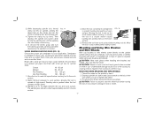
... paddle switch (A). The tool will result. Mounting and Using Depressed Center Grinding Wheels and Sanding Flap Discs MOUNTING AND REMOVING HUBBED WHEELS Hubbed wheels install directly on the spindle. Backing flange is turned off position by pulling and twisting flange away form the machine. 2. To lock the tool on button (J) offers increased FIG. 7 comfort in extended use a wrench to rotate the spindle further. Lift the tool from the work surface. Operate the spindle lock only...
... paddle switch (A). The tool will result. Mounting and Using Depressed Center Grinding Wheels and Sanding Flap Discs MOUNTING AND REMOVING HUBBED WHEELS Hubbed wheels install directly on the spindle. Backing flange is turned off position by pulling and twisting flange away form the machine. 2. To lock the tool on button (J) offers increased FIG. 7 comfort in extended use a wrench to rotate the spindle further. Lift the tool from the work surface. Operate the spindle lock only...
Instruction Manual
Page 17
... remove the wheel, depress the spindle lock button and loosen the threaded clamp nut with included flanges. Refer to operate at high speed. 3. While depressing the spindle lock button, thread the clamp nut (H) on the raised section (pilot) of the spindle by pushing and twisting the flange before touching the tool to the work surface, allowing the tool to page 10-12 for use with the pilot on spindle (Q) with a wrench...
... remove the wheel, depress the spindle lock button and loosen the threaded clamp nut with included flanges. Refer to operate at high speed. 3. While depressing the spindle lock button, thread the clamp nut (H) on the raised section (pilot) of the spindle by pushing and twisting the flange before touching the tool to the work surface, allowing the tool to page 10-12 for use with the pilot on spindle (Q) with a wrench...

Instruction Manual
Page 18
... the use edge grinding/cutting wheels for surface grinding applications because these wheels with surface grinding. Sanding rate is being used for side pressures encountered with a standard Type 27 guard to operate at extra cost from work surface before laying it down. Maintain a 5˚ to stop rotating before turning the tool off . MOUNTING SANDING BACKING PADS (FIG. 14) CAUTION: Proper guard must be reinstalled for more information. Remove the tool from...
... the use edge grinding/cutting wheels for surface grinding applications because these wheels with surface grinding. Sanding rate is being used for side pressures encountered with a standard Type 27 guard to operate at extra cost from work surface before laying it down. Maintain a 5˚ to stop rotating before turning the tool off . MOUNTING SANDING BACKING PADS (FIG. 14) CAUTION: Proper guard must be reinstalled for more information. Remove the tool from...
Instruction Manual
Page 19
... - 180 grit 1. Remove the tool from accessory wheel or cup. Mounting and Using Wire Brushes and Wire Wheels Wire cup brushes or wire wheels screw directly on the grinder spindle without moving, or moving the tool in a circular motion causes 5˚-15˚ burning and swirling marks on may result in various grits. Sanding rate is required when using wire brushes and wheels. To remove the wheel, grasp and turn the backing pad and sanding pad while R depressing the spindle lock button. Coarse grits...
... - 180 grit 1. Remove the tool from accessory wheel or cup. Mounting and Using Wire Brushes and Wire Wheels Wire cup brushes or wire wheels screw directly on the grinder spindle without moving, or moving the tool in a circular motion causes 5˚-15˚ burning and swirling marks on may result in various grits. Sanding rate is required when using wire brushes and wheels. To remove the wheel, grasp and turn the backing pad and sanding pad while R depressing the spindle lock button. Coarse grits...

Instruction Manual
Page 20
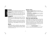
... on the gear case hub. 18 Allowing the tool to operate at high speed. 3. CAUTION: Use extra care when working over an edge, as a sudden sharp movement of the wheel and the work surface. 6. Align the lugs (N) on the guard with this tool (D28140, D28144, D28144N ONLY) and is greatest when the tool operates at high speed. NOTE: All grinders that use Type 1 wheels use are available. Apply minimum pressure to work surface...
... on the gear case hub. 18 Allowing the tool to operate at high speed. 3. CAUTION: Use extra care when working over an edge, as a sudden sharp movement of the wheel and the work surface. 6. Align the lugs (N) on the guard with this tool (D28140, D28144, D28144N ONLY) and is greatest when the tool operates at high speed. NOTE: All grinders that use Type 1 wheels use are available. Apply minimum pressure to work surface...

Instruction Manual
Page 21
... spindle lock button and tighten clamp nut with the raised section (pilot) facing away from power source before installing and removing accessories, before turning tool off and disconnect it down. USING CUTTING WHEELS (FIG. 20) WARNING: Do not use edge grinding/ cutting FIG. 20 wheels for side pressures encountered with clamp lever in the workpiece, do not change backing flange, centering the wheel on the guard. Allow tool to reach full speed before touching tool to work surface before adjusting...
... spindle lock button and tighten clamp nut with the raised section (pilot) facing away from power source before installing and removing accessories, before turning tool off and disconnect it down. USING CUTTING WHEELS (FIG. 20) WARNING: Do not use edge grinding/ cutting FIG. 20 wheels for side pressures encountered with clamp lever in the workpiece, do not change backing flange, centering the wheel on the guard. Allow tool to reach full speed before touching tool to work surface before adjusting...
Instruction Manual
Page 22
... accessories with this product, use identical replacement parts. Recommended accessories for your tool are covered by our: 1 YEAR FREE SERVICE DEWALT will maintain the tool and replace worn parts caused by a DEWALT factory service center, a DEWALT authorized service center or other than those offered by others. Register Online Thank you need assistance in the unlikely event a safety notification is required under the Federal Consumer Safety Act. This warranty does not cover part...
... accessories with this product, use identical replacement parts. Recommended accessories for your tool are covered by our: 1 YEAR FREE SERVICE DEWALT will maintain the tool and replace worn parts caused by a DEWALT factory service center, a DEWALT authorized service center or other than those offered by others. Register Online Thank you need assistance in the unlikely event a safety notification is required under the Federal Consumer Safety Act. This warranty does not cover part...

