
Literature/Product Sheet
Page 1
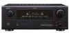
...AVR-887 includes an Auto Set-up to 100MHz, ensuring sharp image quality s 3 sets of component video inputs Connectivity/ Expandability s ASD-1R Control Dock for iPod® (option): Supports iPod playback when connected to the AVR-887 iPod (*1) playback can be enjoyed through the AVR-887 when the ASD-1R, Denon...(equalizer) function that the sound is equipped with a Dock connector. Black version is too strong. A/V Surround Receiver AVR-887 7.1 A/V Surround Receiver features HDMI repeater, conversion, XM-HD Surround and iPod command and control capability. s Supports the most advanced ...
...AVR-887 includes an Auto Set-up to 100MHz, ensuring sharp image quality s 3 sets of component video inputs Connectivity/ Expandability s ASD-1R Control Dock for iPod® (option): Supports iPod playback when connected to the AVR-887 iPod (*1) playback can be enjoyed through the AVR-887 when the ASD-1R, Denon...(equalizer) function that the sound is equipped with a Dock connector. Black version is too strong. A/V Surround Receiver AVR-887 7.1 A/V Surround Receiver features HDMI repeater, conversion, XM-HD Surround and iPod command and control capability. s Supports the most advanced ...
Literature/Product Sheet
Page 2
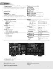
...8569, Japan www.denon.com 16700806 A Inputs FRONT L/R, CENTER, SURROUND L/R, SURROUND BACK L/R, SUBWOOFER 6 Digital Inputs OPTICAL x 4 (incl. IN terminal s Remote In/Out Ports Other features s Audio Delay Function (0 - 200 msec.) s Personal Memory Plus, for Easy Operation The AVR-887 includes the Personal ...FM/XM Random Preset Memory Tuning • Auto Preset Memory (AM/FM) Input/Output Terminals For Every A/V System Audio Inputs 9 sets of Component Video Outputs MONITOR 3 Composite Outputs VCR-1, VCR-2, MONITOR 3 S-Video Outputs VCR-1, VCR-2, MONITOR Specifications Power Amplifier Section...
...8569, Japan www.denon.com 16700806 A Inputs FRONT L/R, CENTER, SURROUND L/R, SURROUND BACK L/R, SUBWOOFER 6 Digital Inputs OPTICAL x 4 (incl. IN terminal s Remote In/Out Ports Other features s Audio Delay Function (0 - 200 msec.) s Personal Memory Plus, for Easy Operation The AVR-887 includes the Personal ...FM/XM Random Preset Memory Tuning • Auto Preset Memory (AM/FM) Input/Output Terminals For Every A/V System Audio Inputs 9 sets of Component Video Outputs MONITOR 3 Composite Outputs VCR-1, VCR-2, MONITOR 3 S-Video Outputs VCR-1, VCR-2, MONITOR Specifications Power Amplifier Section...
Owners Manual - English
Page 4
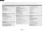
... 40 Calling the settings out 40 Combining the currently playing sound with the desired image (VIDEO SELECT function 40 Personal memory plus function 40 Playing the iPod 40 Listening to music 41 Viewing still pictures and videos (only for choosing the DENON AVR-887 AV Surround Receiver. IN) terminals ... the input signals 30 Surround modes and parameters 31 ~ 33 Using the DENON original surround modes Types of surround modes and their features 34 Selecting the DSP surround simulation 35 Setting the tone control 36 Adjusting the speaker volume 36 Using the fader function ...
... 40 Calling the settings out 40 Combining the currently playing sound with the desired image (VIDEO SELECT function 40 Personal memory plus function 40 Playing the iPod 40 Listening to music 41 Viewing still pictures and videos (only for choosing the DENON AVR-887 AV Surround Receiver. IN) terminals ... the input signals 30 Surround modes and parameters 31 ~ 33 Using the DENON original surround modes Types of surround modes and their features 34 Selecting the DSP surround simulation 35 Setting the tone control 36 Adjusting the speaker volume 36 Using the fader function ...

Owners Manual - English
Page 5
... Advanced Playback Setting the 2ch Direct/Stereo 56 Setting the Dolby Digital Downmix Option Setup 56 Setting the Auto Surround Mode 57 Setting the Manual Equalizer Setup 57 Option Setup Setting the Power Amplifier Assignment 58 Setting the Volume Control 58 Setting the Setup Lock 59 Operating the remote control unit Operating DENON audio components 65 Setting the preset...
... Advanced Playback Setting the 2ch Direct/Stereo 56 Setting the Dolby Digital Downmix Option Setup 56 Setting the Auto Surround Mode 57 Setting the Manual Equalizer Setup 57 Option Setup Setting the Power Amplifier Assignment 58 Setting the Volume Control 58 Setting the Setup Lock 59 Operating the remote control unit Operating DENON audio components 65 Setting the preset...
Owners Manual - English
Page 6
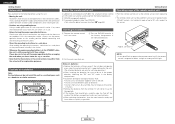
...(The attached batteries are not problems with the connection cables. Check once again that all other than DENON: • Set using the preset memory function ( page 65). Notes on . Wall 3 ENGLISH Always set does not operate even when the remote control unit is in use. • Before turning the ...in the STANDBY state, the unit is exposed to direct sunlight or strong artificial light. Cautions on . Note In addition to controlling the AVR-887, the attached remote control unit (RC-1043) can be difficult to operate the remote control unit if the remote sensor is still connected ...
...(The attached batteries are not problems with the connection cables. Check once again that all other than DENON: • Set using the preset memory function ( page 65). Notes on . Wall 3 ENGLISH Always set does not operate even when the remote control unit is in use. • Before turning the ...in the STANDBY state, the unit is exposed to direct sunlight or strong artificial light. Cautions on . Note In addition to controlling the AVR-887, the attached remote control unit (RC-1043) can be difficult to operate the remote control unit if the remote sensor is still connected ...
Owners Manual - English
Page 7
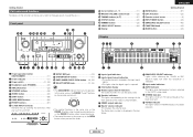
...output indicator u Master volume indicator This displays the volume level. The Setup item number is inputted. t Speaker indicators This lights corresponding to the settings of the front speakers of these parts, refer to use them. !2 SETUP MIC jack 10) !3 SYSTEM SETUP button 11) !4 SURR....operates in the AUTO tuning mode. !1 STEREO indicator This lights when an FM stereo broadcast has been received. !2 TUNED indicator This lights when an FM/AM broadcast has been received. 4 ENGLISH MODE/SURR. e Information display r Output signal channel indicators The audio channels that can ...
...output indicator u Master volume indicator This displays the volume level. The Setup item number is inputted. t Speaker indicators This lights corresponding to the settings of the front speakers of these parts, refer to use them. !2 SETUP MIC jack 10) !3 SYSTEM SETUP button 11) !4 SURR....operates in the AUTO tuning mode. !1 STEREO indicator This lights when an FM stereo broadcast has been received. !2 TUNED indicator This lights when an FM/AM broadcast has been received. 4 ENGLISH MODE/SURR. e Information display r Output signal channel indicators The audio channels that can ...
Owners Manual - English
Page 10
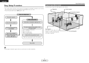
...Setup Procedure Surround back speaker Placing the speakers. Auto setup flow Connecting the speakers. Connecting a microphone ( page 10). Connect the AVR-887's monitor output terminal to setup flow Speaker layout [Basic layout] Example of basic layout with the front of the monitor or ... measurement result. Connect the DVD player to your listening room environment and the source equipment and loudspeakers you are using. • To set the sound field manually ( page 60 ~ 63). Store the measurement result in the listening position. 1) Speaker Configuration 2) Distance 3)...
...Setup Procedure Surround back speaker Placing the speakers. Auto setup flow Connecting the speakers. Connecting a microphone ( page 10). Connect the AVR-887's monitor output terminal to setup flow Speaker layout [Basic layout] Example of basic layout with the front of the monitor or ... measurement result. Connect the DVD player to your listening room environment and the source equipment and loudspeakers you are using. • To set the sound field manually ( page 60 ~ 63). Store the measurement result in the listening position. 1) Speaker Configuration 2) Distance 3)...

Owners Manual - English
Page 11
... check the wiring of the speaker cable come in and turn the unit's power back on . Center speaker >< Subwoofer Connection terminal for the set to rise, activating the protection circuit. Either tightly twist or terminate the core wires. 2. When the protection circuit is on . IN Surround ... cable conductors, or with >). If the protection circuit is cut off the power and contact a DENON service center. ENGLISH Easy Setup Procedure ¢ Connections • With the AVR-887, up to the left channel. 8 ENGLISH Connecting the speaker cables 1. Insert the cable. 3. ...
... check the wiring of the speaker cable come in and turn the unit's power back on . Center speaker >< Subwoofer Connection terminal for the set to rise, activating the protection circuit. Either tightly twist or terminate the core wires. 2. When the protection circuit is on . IN Surround ... cable conductors, or with >). If the protection circuit is cut off the power and contact a DENON service center. ENGLISH Easy Setup Procedure ¢ Connections • With the AVR-887, up to the left channel. 8 ENGLISH Connecting the speaker cables 1. Insert the cable. 3. ...

Owners Manual - English
Page 13
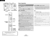
... SETUP D H F G ENTER SYSTEM SETUP D H F G, ENTER [ON/SOURCE] ENTER D H F G ENGLISH Auto Setup/Room Equalizer (Room EQ) Functions • The AVR-887's auto setup and room equalizer functions use the attached microphone to measure the acoustic properties in the room and automatically make the sound field... Buttons on the remote control unit Button name only : Buttons on a camera tripod, etc., and set with the receptor pointing towards the ceiling. • To make the optimum settings. • When the auto setup procedure is performed, one of the following three correction curves can be...
... SETUP D H F G ENTER SYSTEM SETUP D H F G, ENTER [ON/SOURCE] ENTER D H F G ENGLISH Auto Setup/Room Equalizer (Room EQ) Functions • The AVR-887's auto setup and room equalizer functions use the attached microphone to measure the acoustic properties in the room and automatically make the sound field... Buttons on the remote control unit Button name only : Buttons on a camera tripod, etc., and set with the receptor pointing towards the ceiling. • To make the optimum settings. • When the auto setup procedure is performed, one of the following three correction curves can be...

Owners Manual - English
Page 14
... Turn on . Front A Front B Front A+B 11 ENGLISH The message "Connect Microphone" is displayed if no microphone is not displayed when using headphones. Set the volume to halfway and set . e Perform the Auto Setup procedure 1 Press SYSTEM SETUP. 2 Press D H to select "Auto Setup / Room EQ", then press ENTER. 3 ... to use the "Front A" or "Front B" speakers with bi-amp connections. Some subwoofers have a standby mode. Surround Back: Assign to set the crossover frequency to select "Auto Setup", then press ENTER. During the auto setup procedure, test tones are not output to "ZONE2...
... Turn on . Front A Front B Front A+B 11 ENGLISH The message "Connect Microphone" is displayed if no microphone is not displayed when using headphones. Set the volume to halfway and set . e Perform the Auto Setup procedure 1 Press SYSTEM SETUP. 2 Press D H to select "Auto Setup / Room EQ", then press ENTER. 3 ... to use the "Front A" or "Front B" speakers with bi-amp connections. Some subwoofers have a standby mode. Surround Back: Assign to set the crossover frequency to select "Auto Setup", then press ENTER. During the auto setup procedure, test tones are not output to "ZONE2...

Owners Manual - English
Page 15
...can be possible if there are nearby. • Proper measurements may not be checked here. 2 After checking, press ENTER, then press D H to set at "Setting the Power Amplifier Assignment" ( page 58). • After each channel is performed as follows: FL FR 1 2 C SW SL SR SBL SBR... the room. ENGLISH Easy Setup Procedure y Starting Auto Setup Press D H to two times. The measurement results of air- Store: All the settings are output during the measurements. Easy Setup Procedure u Checking and storing the measurement results 1 Press D H to the Auto Setup check screen automatically...
...can be possible if there are nearby. • Proper measurements may not be checked here. 2 After checking, press ENTER, then press D H to set at "Setting the Power Amplifier Assignment" ( page 58). • After each channel is performed as follows: FL FR 1 2 C SW SL SR SBL SBR... the room. ENGLISH Easy Setup Procedure y Starting Auto Setup Press D H to two times. The measurement results of air- Store: All the settings are output during the measurements. Easy Setup Procedure u Checking and storing the measurement results 1 Press D H to the Auto Setup check screen automatically...

Owners Manual - English
Page 16
... items, and measure again. • When there is • Check the polarity of the pertinent speakers. r This screen will be displayed when accurate measurements • Set up the speakers so that the pertinent speakers are properly connected. Example Cause Measures q This screen will be displayed even though the speakers are properly...
... items, and measure again. • When there is • Check the polarity of the pertinent speakers. r This screen will be displayed when accurate measurements • Set up the speakers so that the pertinent speakers are properly connected. Example Cause Measures q This screen will be displayed even though the speakers are properly...

Owners Manual - English
Page 18
... terminals) (S-Video terminal) (Component Video terminals) (S-Video terminal) (Video terminal) AVR-887's input terminals (Video terminal) AVR-887's output terminals : only 480i/576i Connecting Other Sources Relationship between the video input ...signal and monitor output according to the video convert settings Video convert ON Input signals HDMI E E E E E E E E E E E E E E E E COMPONENT E E E E C (1080p) C (480p ~ 720p) C (480i/576i) C (1080p) C (480p ...
... terminals) (S-Video terminal) (Component Video terminals) (S-Video terminal) (Video terminal) AVR-887's input terminals (Video terminal) AVR-887's output terminals : only 480i/576i Connecting Other Sources Relationship between the video input ...signal and monitor output according to the video convert settings Video convert ON Input signals HDMI E E E E E E E E E E E E E E E E COMPONENT E E E E C (1080p) C (480p ~ 720p) C (480i/576i) C (1080p) C (480p ...

Owners Manual - English
Page 19
... display is displayed when the "Analog to HDMI convert" is set the player's resolution to one which the monitor is compatible can handle. • Video down conversion to HDMI conversion function • The AVR-887's video up-conversion function lets you output analog video input signals...Because of this, if the monitor equipped with HDMI terminal is compatible with the 480i/576i resolution, all the signals the AVR-887 handles can be checked using a component cable and set to the monitor with a single HDMI cable. • If your monitor is compatible with a resolution of 480i/576i....
... display is displayed when the "Analog to HDMI convert" is set the player's resolution to one which the monitor is compatible can handle. • Video down conversion to HDMI conversion function • The AVR-887's video up-conversion function lets you output analog video input signals...Because of this, if the monitor equipped with HDMI terminal is compatible with the 480i/576i resolution, all the signals the AVR-887 handles can be checked using a component cable and set to the monitor with a single HDMI cable. • If your monitor is compatible with a resolution of 480i/576i....

Owners Manual - English
Page 20
... to use the coaxial connection, it needs to your monitor is equipped with an HDMI terminal, connect the AVR-887 to the monitor using digital audio connections, assign the digital terminal (coaxial or optical) at "Setting the Digital In Assignment" ( page 49). TV/DBS tuner H COMPONENT VIDEO OUT Y PB PR A AUDIO OUT L L L R R... optical connections. ENGLISH Connecting Other Sources Connecting equipment with HDMI terminals [To convert analog video signals to HDMI signals] • The AVR-887 is not equipped with a function for converting analog video signals into HDMI signals.
... to use the coaxial connection, it needs to your monitor is equipped with an HDMI terminal, connect the AVR-887 to the monitor using digital audio connections, assign the digital terminal (coaxial or optical) at "Setting the Digital In Assignment" ( page 49). TV/DBS tuner H COMPONENT VIDEO OUT Y PB PR A AUDIO OUT L L L R R... optical connections. ENGLISH Connecting Other Sources Connecting equipment with HDMI terminals [To convert analog video signals to HDMI signals] • The AVR-887 is not equipped with a function for converting analog video signals into HDMI signals.

Owners Manual - English
Page 22
...LINEAR PCM PACKED PCM (with CPPM / C without CPPM) CD LINEAR PCM C Multi area E Super Audio CD Stereo area E CD area C The AVR-887 is HDMI Ver. 1.1 compatible. ¢ Copyright Protection System To play DVD-Audio discs that are copyright protected by the equipment that support HDMI, some ... can handle. • Use a cable including the HDMI logo (HDMI certified product) for more information about this case, change the setting of the resolution on the combination of the partner equipment. In this . Connecting Other Sources NOTE: • The audio signals on the...
...LINEAR PCM PACKED PCM (with CPPM / C without CPPM) CD LINEAR PCM C Multi area E Super Audio CD Stereo area E CD area C The AVR-887 is HDMI Ver. 1.1 compatible. ¢ Copyright Protection System To play DVD-Audio discs that are copyright protected by the equipment that support HDMI, some ... can handle. • Use a cable including the HDMI logo (HDMI certified product) for more information about this case, change the setting of the resolution on the combination of the partner equipment. In this . Connecting Other Sources NOTE: • The audio signals on the...

Owners Manual - English
Page 23
... the component video connection, it needs to 2) OUT terminal. If you choose to use the optical connection, it is necessary that is connected to the AVR-887 VCR-1 (to 2) OUTPUT terminal. For more information about Component Input Assignment ( page 53). Example: VCR-1 IN → S-Video cable : VCR-2 OUT → S-Video cable VCR...; Video cable : VCR-1 OUT → Video cable 20 ENGLISH The source selected in addition to your DVD recorder. S-Video and composite video outputs are two sets of cable used with the output from the digital output terminal (OPT-3).
... the component video connection, it needs to 2) OUT terminal. If you choose to use the optical connection, it is necessary that is connected to the AVR-887 VCR-1 (to 2) OUTPUT terminal. For more information about Component Input Assignment ( page 53). Example: VCR-1 IN → S-Video cable : VCR-2 OUT → S-Video cable VCR...; Video cable : VCR-1 OUT → Video cable 20 ENGLISH The source selected in addition to your DVD recorder. S-Video and composite video outputs are two sets of cable used with the output from the digital output terminal (OPT-3).

Owners Manual - English
Page 24
... L L L R R R D OPTICAL OUT D OPTICAL IN • The source selected for MAIN ZONE is DENON ASD-1R sold separately) and the DOCK CONTROL jack on the AVR- 887's rear panel to any AUDIO and/or S-VIDEO terminal(s). For instructions on playing the iPod, see "Setting the iPod Assignment" ( page 50). iPod ASD-1R A R R L L AUDIO OUT G S-VIDEO... need to connect the analog inputs and outputs as shown below shows an example of the component connected to the OPTICAL 3 OUT terminal on the AVR-887 with the output from the digital output terminal (OPT-3).
... L L L R R R D OPTICAL OUT D OPTICAL IN • The source selected for MAIN ZONE is DENON ASD-1R sold separately) and the DOCK CONTROL jack on the AVR- 887's rear panel to any AUDIO and/or S-VIDEO terminal(s). For instructions on playing the iPod, see "Setting the iPod Assignment" ( page 50). iPod ASD-1R A R R L L AUDIO OUT G S-VIDEO... need to connect the analog inputs and outputs as shown below shows an example of the component connected to the OPTICAL 3 OUT terminal on the AVR-887 with the output from the digital output terminal (OPT-3).

Owners Manual - English
Page 26
... the MULTI ZONE terminals For instructions on installation and operation of separately sold separately room-to-room remote control unit (DENON RC-616, 617 or 618) is wired and connected between the MAIN ZONE and ZONE2, the remote-controllable devices ... sold devices, refer to the devices' operating instructions. 23 ENGLISH (L) (R) >< Front speakers (B) (L) (R) >< Front speakers (A) (L) (R) > < ZONE2 Front speakers The settings must be used as the ZONE2 speaker out terminals ( page 58). • The connections diagram below is an example for when the surround back speaker...
... the MULTI ZONE terminals For instructions on installation and operation of separately sold separately room-to-room remote control unit (DENON RC-616, 617 or 618) is wired and connected between the MAIN ZONE and ZONE2, the remote-controllable devices ... sold devices, refer to the devices' operating instructions. 23 ENGLISH (L) (R) >< Front speakers (B) (L) (R) >< Front speakers (A) (L) (R) > < ZONE2 Front speakers The settings must be used as the ZONE2 speaker out terminals ( page 58). • The connections diagram below is an example for when the surround back speaker...
Owners Manual - English
Page 28
... indicator does not light, check whether the "Digital In Assignment" ( page 49) and connections are input. NOTE: • When the input mode is set the input mode. • The "DIGITAL" indicator lights when digital signals are being input. To select the input source when ZONE2/REC SELECT is selected... the "AUTO" mode, noise may seen strong. ATT". For some players the playback level of input signal is detected and the AVR-887's surround mode is connected first, then set . If so, set . • In play in the "ANALOG" or "PCM" mode. • When playing DTS signals in the EXT. IN),...
... indicator does not light, check whether the "Digital In Assignment" ( page 49) and connections are input. NOTE: • When the input mode is set the input mode. • The "DIGITAL" indicator lights when digital signals are being input. To select the input source when ZONE2/REC SELECT is selected... the "AUTO" mode, noise may seen strong. ATT". For some players the playback level of input signal is detected and the AVR-887's surround mode is connected first, then set . If so, set . • In play in the "ANALOG" or "PCM" mode. • When playing DTS signals in the EXT. IN),...


