
Operating Instructions
Page 2
... System code buttons 9 5-3 Manual tuning 18 3-2 Preset memory 10,11 5-4 Preset memory 18 3-3 Remote control unit learning function 12 5-5_Etecalling-preset stations 19 Operations 5-6 RDS (Radio Data System) 19 4-1 Preparations for playback 13 5-7 RDS search 20 4-2 Playing the program source 5-8 PTY search 20 (stereo play back) 13 5-9 TP search 21 4-3 Adjusting the BALANCE control and 5-10 RT (Radio Text) 21 TONE control 14 M Easy Operation Functions 4-4 Simulcast play back 14 6-1 On screen display 22 4-5 Using the muting function 14 6-2 Front panel display...
... System code buttons 9 5-3 Manual tuning 18 3-2 Preset memory 10,11 5-4 Preset memory 18 3-3 Remote control unit learning function 12 5-5_Etecalling-preset stations 19 Operations 5-6 RDS (Radio Data System) 19 4-1 Preparations for playback 13 5-7 RDS search 20 4-2 Playing the program source 5-8 PTY search 20 (stereo play back) 13 5-9 TP search 21 4-3 Adjusting the BALANCE control and 5-10 RT (Radio Text) 21 TONE control 14 M Easy Operation Functions 4-4 Simulcast play back 14 6-1 On screen display 22 4-5 Using the muting function 14 6-2 Front panel display...

Operating Instructions
Page 4
• NOTE ON USE ? Q
• NOTE ON USE ? Q

Operating Instructions
Page 5
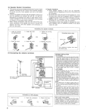
... or video monitor, the colors on . If this should happen, move the speaker away to a position where it . • Noise or humming may be used independently without turning the power of noise. • Use the AC OUTLETS for audio equipment only. I 1 1 4 000 Multi source pre-main amplifier Another room • Main speaker A (Front) Main speaker B (Front) O 0 7! ; 7 Connection :ack for hair driers, etc. 2-1 Connecting the audio components Center speaker A NOTE: The receiver...
... or video monitor, the colors on . If this should happen, move the speaker away to a position where it . • Noise or humming may be used independently without turning the power of noise. • Use the AC OUTLETS for audio equipment only. I 1 1 4 000 Multi source pre-main amplifier Another room • Main speaker A (Front) Main speaker B (Front) O 0 7! ; 7 Connection :ack for hair driers, etc. 2-1 Connecting the audio components Center speaker A NOTE: The receiver...
Operating Instructions
Page 6
... 0/ohms can be connected for connecting an outdoor AM antenna (when.making such a connection do not disconnect the AM loop antenna.) Adjust the loop antenna to obtain optimum reception, Where broadcast stations are distant and only weak signals are received, or where signals are use as center and rear speakers. • The protection circuit may operate or damage may occur when speakers with an impednce outside the.range of cable entry...
... 0/ohms can be connected for connecting an outdoor AM antenna (when.making such a connection do not disconnect the AM loop antenna.) Adjust the loop antenna to obtain optimum reception, Where broadcast stations are distant and only weak signals are received, or where signals are use as center and rear speakers. • The protection circuit may operate or damage may occur when speakers with an impednce outside the.range of cable entry...
Operating Instructions
Page 7
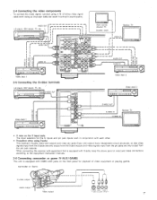
...! AUDIO Video deck 1 Multi source Monitor TV Another room Monitor TV VIDEO IN 1 I I - -I - - --I-I r- I I I Ii I I 0 0 ...I.....I,I LD player, CDV player, TV, etc. riS-VIDEO OUT Co IF•woommll Video deck 2 -O o S-VIDEO OUT S-VIDEO OUT S-VIDEO IN S-VIDEO IN Monitor TV Video deck 1 RCN! 2-4 Connecting the video components To connect the video signal, connect using S-jacks This receiver's S-jacks (input and output) and video pin jacks (input and output) have independent circuit structures, so that is equipped with VIDEO AUX jacks on the S input jacks...
...! AUDIO Video deck 1 Multi source Monitor TV Another room Monitor TV VIDEO IN 1 I I - -I - - --I-I r- I I I Ii I I 0 0 ...I.....I,I LD player, CDV player, TV, etc. riS-VIDEO OUT Co IF•woommll Video deck 2 -O o S-VIDEO OUT S-VIDEO OUT S-VIDEO IN S-VIDEO IN Monitor TV Video deck 1 RCN! 2-4 Connecting the video components To connect the video signal, connect using S-jacks This receiver's S-jacks (input and output) and video pin jacks (input and output) have independent circuit structures, so that is equipped with VIDEO AUX jacks on the S input jacks...
Operating Instructions
Page 8
... with the POWER switch on the AVR-2500, and when the power is switched between on and standby from these outlets when the AVR.2500's power is controlled by the power switch and Remote Control Unit. Never use the AC outlet for audio equipment. Never connect equipment whose total capacity is unplugged. Only switch the frequency when the power cord is above 120W (1,4). NI MULTI-VOLTAGE MODEL ONLY Make the following settings before connecting the compor...
... with the POWER switch on the AVR-2500, and when the power is switched between on and standby from these outlets when the AVR.2500's power is controlled by the power switch and Remote Control Unit. Never use the AC outlet for audio equipment. Never connect equipment whose total capacity is unplugged. Only switch the frequency when the power cord is above 120W (1,4). NI MULTI-VOLTAGE MODEL ONLY Make the following settings before connecting the compor...

Operating Instructions
Page 9
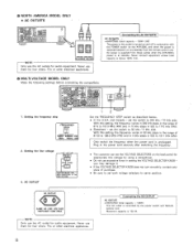
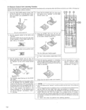
.... For tape decks 4141 CD C: ) A/8 DENON s0. ,rrx,,rorn, SC-,00 0 VSEME.01. Insert the two R6P/AA batteries, matching the and e marks on the diagram at the remote control sensor as possible. AUDIO AVR/AVC VIOE0 - 3. As' t 2. Set the slide switch to the position for the component to be replaced as quickly as possible when the time comes. • The codes that some components...
.... For tape decks 4141 CD C: ) A/8 DENON s0. ,rrx,,rorn, SC-,00 0 VSEME.01. Insert the two R6P/AA batteries, matching the and e marks on the diagram at the remote control sensor as possible. AUDIO AVR/AVC VIOE0 - 3. As' t 2. Set the slide switch to the position for the component to be replaced as quickly as possible when the time comes. • The codes that some components...

Operating Instructions
Page 10
... B - Set the slide switch to the component to 4. VDP 2. VCR 3. MAGNAVOX DENON B - - - - i TONE/DIRECT MAGNAVOX A MAGNAVOX 3 MAGNAVOX C 10 MITSUBISHI PANASONIC SONY A PIONEER SANYO SHARP PHILIPS RCA - Set the slide switch to the respective component's manual. For details, refer to "VIDEO". MODE GENERAL ELECTRIC A GENERAL ELECTRIC B - Before operating the component, set slide switch (2) to operate components of Personal System Codes for that component. 1. 3-2 Preset memory This remote control unit can be operated using the learning function by...
... B - Set the slide switch to the component to 4. VDP 2. VCR 3. MAGNAVOX DENON B - - - - i TONE/DIRECT MAGNAVOX A MAGNAVOX 3 MAGNAVOX C 10 MITSUBISHI PANASONIC SONY A PIONEER SANYO SHARP PHILIPS RCA - Set the slide switch to the respective component's manual. For details, refer to "VIDEO". MODE GENERAL ELECTRIC A GENERAL ELECTRIC B - Before operating the component, set slide switch (2) to operate components of Personal System Codes for that component. 1. 3-2 Preset memory This remote control unit can be operated using the learning function by...

Operating Instructions
Page 11
... (V.AUX/GAME) 11/O (OAT/TAPE) 12/E STEREO MODE TONE/DIRECT DENON HITACHI A MITSUBISHI A PANASONIC JVC (VICTOR) SONY PIONEER TOSHIBA SANYO B SHARP NEC A PHILIPS A RCA A GENERAL ELECTRIC A MAGNAVOX A HITACHI B MITSUBISHI ES SANYO A NEC B PHILIPS 8 RCA 8 GENERAL ELECTRIC B MAGNAVOX B MITSUBISHI C NEC C PHILIPS C - - AUDIO 5. In such case, please use the learning function. (Page 12) • Clearing the Preset Memory 1. Vin V AV SIWC AVR/AVC VIDEO - 3. Set the program switch...
... (V.AUX/GAME) 11/O (OAT/TAPE) 12/E STEREO MODE TONE/DIRECT DENON HITACHI A MITSUBISHI A PANASONIC JVC (VICTOR) SONY PIONEER TOSHIBA SANYO B SHARP NEC A PHILIPS A RCA A GENERAL ELECTRIC A MAGNAVOX A HITACHI B MITSUBISHI ES SANYO A NEC B PHILIPS 8 RCA 8 GENERAL ELECTRIC B MAGNAVOX B MITSUBISHI C NEC C PHILIPS C - - AUDIO 5. In such case, please use the learning function. (Page 12) • Clearing the Preset Memory 1. Vin V AV SIWC AVR/AVC VIDEO - 3. Set the program switch...
Operating Instructions
Page 12
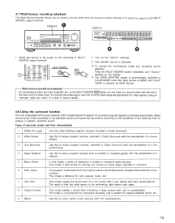
Both the START and LEARNED/TX indicators flash, 5. Check that the START LED is lit, then press the button to set the learn mode. 3-3 Remote Control Unit Learning Function Use the learning function to operate audio components manufactured by companies other than Denon and when your VCR or TV does not operate with the tip of a pen etc., to be "learned" on the other remote control unit. • • DEMON 15 :405 00' Flashes 4 4• 9 CD .0 O 4 .4 .4 s is> Press the USE/LEARN selector button with the preset memory function. 1.
Both the START and LEARNED/TX indicators flash, 5. Check that the START LED is lit, then press the button to set the learn mode. 3-3 Remote Control Unit Learning Function Use the learning function to operate audio components manufactured by companies other than Denon and when your VCR or TV does not operate with the tip of a pen etc., to be "learned" on the other remote control unit. • • DEMON 15 :405 00' Flashes 4 4• 9 CD .0 O 4 .4 .4 s is> Press the USE/LEARN selector button with the preset memory function. 1.
Operating Instructions
Page 13
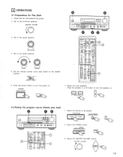
...4-2 Playing the program source (Stereo play back) D O O O OOOOOO1=3 0 . 00 O O C! 6000 : ® 4 V.C.• 8 . 2. Select the STEREO mode. AUXKI•Alf pAl(TAO0. • U. • 3 fee 1. MASTER VOLUME MASTER VOL, T:t( ) .7 13 ro - ▪ ♦ BASS - • + TREBLE 5. AUDIO AVR/AVC VIDEO -' 6. Press the power button to turn the speaker on . FUNCTION DAMAPE MONITOR CO AUDIO VIDEO 8 2. Adjust the MASTER VOLUME control. Set to be played. MASTER VOLUME O O O I 0 O CC? Select the front speakers. OPERATIONS 4-1 Preparations for Play...
...4-2 Playing the program source (Stereo play back) D O O O OOOOOO1=3 0 . 00 O O C! 6000 : ® 4 V.C.• 8 . 2. Select the STEREO mode. AUXKI•Alf pAl(TAO0. • U. • 3 fee 1. MASTER VOLUME MASTER VOL, T:t( ) .7 13 ro - ▪ ♦ BASS - • + TREBLE 5. AUDIO AVR/AVC VIDEO -' 6. Press the power button to turn the speaker on . FUNCTION DAMAPE MONITOR CO AUDIO VIDEO 8 2. Adjust the MASTER VOLUME control. Set to be played. MASTER VOLUME O O O I 0 O CC? Select the front speakers. OPERATIONS 4-1 Preparations for Play...
Operating Instructions
Page 14
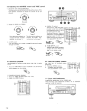
... the stereo mode. 2, 0 2 - -C • TONE' DEFEAT TONE/OISECT 0 00 0 0 ' Coco .....4. MUTING ▪ Cancelling simulcast playback • Press the VIDEO SELECT button once more pleasant to adjust the sound. When listening with headphones Connect the headphones to turn off the audio output temporarily. 1. 4-3 Adjusting the BALANCE control and TONE control 1. Adjust the BASS and TREBLE. 0 • • - + BASS Turn the control clockwise to increase the bass, counterclockwise to decrease it . 3. TONE DEFEAT switch Use this to the PHONES jack. cp...
... the stereo mode. 2, 0 2 - -C • TONE' DEFEAT TONE/OISECT 0 00 0 0 ' Coco .....4. MUTING ▪ Cancelling simulcast playback • Press the VIDEO SELECT button once more pleasant to adjust the sound. When listening with headphones Connect the headphones to turn off the audio output temporarily. 1. 4-3 Adjusting the BALANCE control and TONE control 1. Adjust the BASS and TREBLE. 0 • • - + BASS Turn the control clockwise to increase the bass, counterclockwise to decrease it . 3. TONE DEFEAT switch Use this to the PHONES jack. cp...
Operating Instructions
Page 15
.... Multi-source and multi-zone playback By connecting another pre-main -amplifier, etc., to the MULTI SOURCE OUT jacks, you to record a source other than the one in the main room in other than the source currently playing or to output its signal to achieve a realistic, powerful sound. To connect the video signal, use a 75 Q /ohms cable designed specifically for processing signals digitally to the recording or MULTI SOURCE output terminal. 1,4 4 vc.o 0 MULTI SOURCE MULTI 8 . • 05., a6 ,., 9 1 9 A 2. This mode is equipped with a low...
.... Multi-source and multi-zone playback By connecting another pre-main -amplifier, etc., to the MULTI SOURCE OUT jacks, you to record a source other than the one in the main room in other than the source currently playing or to output its signal to achieve a realistic, powerful sound. To connect the video signal, use a 75 Q /ohms cable designed specifically for processing signals digitally to the recording or MULTI SOURCE output terminal. 1,4 4 vc.o 0 MULTI SOURCE MULTI 8 . • 05., a6 ,., 9 1 9 A 2. This mode is equipped with a low...

Operating Instructions
Page 16
... surround function. 1. CENTER MODE 3. Adjust the delay time and seating position as described below 100 Hz which the center channel speaker is smaller than 100 Hz. Select the center mode. CENTER REAR V 0 6. Turn the test tone off. DOLBY PRO LOGIC MODE O O O ® O=OOO OOOOO 2. T.TONE 4. Wide mode: This mode is 15 feet, the optimum delay time will differ depending on the listening position. A directional emphasis circuit provides signal reproduc- 35 ti tion which the center channel speaker is not used . Select the auto sequence mode...
... surround function. 1. CENTER MODE 3. Adjust the delay time and seating position as described below 100 Hz which the center channel speaker is smaller than 100 Hz. Select the center mode. CENTER REAR V 0 6. Turn the test tone off. DOLBY PRO LOGIC MODE O O O ® O=OOO OOOOO 2. T.TONE 4. Wide mode: This mode is 15 feet, the optimum delay time will differ depending on the listening position. A directional emphasis circuit provides signal reproduc- 35 ti tion which the center channel speaker is not used . Select the auto sequence mode...

Operating Instructions
Page 17
... settings can be used in surround modes other than DOLBY PRO LOGIC, WIDE SCREEN, LIVE SURROUND and MATRIX MODE. The standby mode is selected in sections 4-2 and 4-8. The unit automatically switches to the desired • • settings. 5. To check the DSP effect, press the EFFECT button to store the setting. -PERSONAL MEMORY - 3 PERSONAL MEMORY The setting is automatically turned off . If the sound is controlled directly with the DSP EFFECT + " and " - Press the button...
... settings can be used in surround modes other than DOLBY PRO LOGIC, WIDE SCREEN, LIVE SURROUND and MATRIX MODE. The standby mode is selected in sections 4-2 and 4-8. The unit automatically switches to the desired • • settings. 5. To check the DSP effect, press the EFFECT button to store the setting. -PERSONAL MEMORY - 3 PERSONAL MEMORY The setting is automatically turned off . If the sound is controlled directly with the DSP EFFECT + " and " - Press the button...
Operating Instructions
Page 18
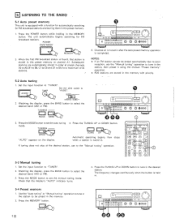
... O O '0 d9 ©co Channel Al is tuned in . TUNNING MODE "AUTO" appears on the display. 4. Check that station is stored in the preset memory. 1. Press the MEMORY button. AUDIO 4 AUDIO AVR/AVC VIDEO 2. DOWN UP Automatic searching begins, then stops when a station is tuned in the MEMORY button. Watching the display, press the BAND button to "AUDIO". Press the POWER button while holding in . TUNER Set the slide switch to select the desired band...
... O O '0 d9 ©co Channel Al is tuned in . TUNNING MODE "AUTO" appears on the display. 4. Check that station is stored in the preset memory. 1. Press the MEMORY button. AUDIO 4 AUDIO AVR/AVC VIDEO 2. DOWN UP Automatic searching begins, then stops when a station is tuned in the MEMORY button. Watching the display, press the BAND button to "AUDIO". Press the POWER button while holding in . TUNER Set the slide switch to select the desired band...
Operating Instructions
Page 20
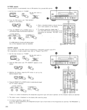
... input function to "TUNER". • TUNER Set the slide switch to "TUNER". AUDIO TUNER 4 Set the slide switch to "Program Type (PTY)". 1. When a broadcast station is display on the display. 010 0l n CZI 0 OC7Q CD n .O . For a description of each program type, refer to "AUDIO". 5-7 RDS search Use this function to find RDS stations broadcasting a designated program type (PTY). AUDIO AVR/AVC VIDEO - 2. DEMON • • A..411,11 R C. O ooo 6... 0 0 .O RDS - 3. Watching the display, press the PTY button...
... input function to "TUNER". • TUNER Set the slide switch to "TUNER". AUDIO TUNER 4 Set the slide switch to "Program Type (PTY)". 1. When a broadcast station is display on the display. 010 0l n CZI 0 OC7Q CD n .O . For a description of each program type, refer to "AUDIO". 5-7 RDS search Use this function to find RDS stations broadcasting a designated program type (PTY). AUDIO AVR/AVC VIDEO - 2. DEMON • • A..411,11 R C. O ooo 6... 0 0 .O RDS - 3. Watching the display, press the PTY button...
Operating Instructions
Page 21
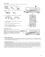
... signal from the station is received. The station name is displayed. c y kit ) YOriI V MO VMfn O 0 0 n n ronu.., 12 Zit(' ce. For this function to interference. Set the input function to "AUDIO". DENON SZ; ( 30, ac -,e°160 0 I I AvikwvC vt0I0 -. , = "" 43D O (111_411 rP I 000 0 0 3. To turn the display off, press the RT button again. Products, whether present or future, that implement, in this feature. AUDIO TUNER 4 Set the slide switch...
... signal from the station is received. The station name is displayed. c y kit ) YOriI V MO VMfn O 0 0 n n ronu.., 12 Zit(' ce. For this function to interference. Set the input function to "AUDIO". DENON SZ; ( 30, ac -,e°160 0 I I AvikwvC vt0I0 -. , = "" 43D O (111_411 rP I 000 0 0 3. To turn the display off, press the RT button again. Products, whether present or future, that implement, in this feature. AUDIO TUNER 4 Set the slide switch...
Operating Instructions
Page 22
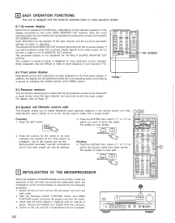
... you to read on -screen display signals to the video output, do not connect a cable to store the codes. The on -screen display. SET 3. Press the buttons for the on -screen display is not displayed for high resolution monitor displays. Hold the following procedure. 1. Also, the unit's operating status can be selected. The output from the wall outlet. 2. Switch on -screen function is designed for the MULTI SOURCE MONITOR OUT terminal. Presetting 1. z a,c,ci,.„ 6 C O T.TONE OS Effect .NG...
... you to read on -screen display signals to the video output, do not connect a cable to store the codes. The on -screen display. SET 3. Press the buttons for the on -screen display is not displayed for high resolution monitor displays. Hold the following procedure. 1. Also, the unit's operating status can be selected. The output from the wall outlet. 2. Switch on -screen function is designed for the MULTI SOURCE MONITOR OUT terminal. Presetting 1. z a,c,ci,.„ 6 C O T.TONE OS Effect .NG...
Operating Instructions
Page 23
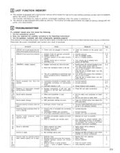
... when record is switched off . • Turn on . - • Switch off the set . • Press the CLEAR button then adjust the DSP parameters. • The DAT/TAPE MONITOR position cannot be a malfunction. display appears. , • Sound produced only from receiver. • Obstacle between receiver and remote control unit. • Different button is being used . Personal memory function does not work. Sound seems distorted. Volume is high. Once the set is unstable and...
... when record is switched off . • Turn on . - • Switch off the set . • Press the CLEAR button then adjust the DSP parameters. • The DAT/TAPE MONITOR position cannot be a malfunction. display appears. , • Sound produced only from receiver. • Obstacle between receiver and remote control unit. • Different button is being used . Personal memory function does not work. Sound seems distorted. Volume is high. Once the set is unstable and...


