Service Manual
Page 1
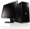
... and Windows are either the entities claiming the marks and names or their products. Dell™ Inspiron™ 535/537/545/546 Service Manual Technical Overview Before You Begin Computer Cover Front Bezel Memory PCI and PCI Express Cards Drives Models DCME and DCMF Fans Front I/O Panel Processor System Board Power Supply Battery System Setup Notes, Cautions, and Warnings NOTE: A NOTE indicates important information that helps you make better use of data if instructions are...
... and Windows are either the entities claiming the marks and names or their products. Dell™ Inspiron™ 535/537/545/546 Service Manual Technical Overview Before You Begin Computer Cover Front Bezel Memory PCI and PCI Express Cards Drives Models DCME and DCMF Fans Front I/O Panel Processor System Board Power Supply Battery System Setup Notes, Cautions, and Warnings NOTE: A NOTE indicates important information that helps you make better use of data if instructions are...

Service Manual
Page 2
... be replaced or-if purchased separately-installed by your computer. Shut down your operating system, press and hold the power button for removing and installing the components in reverse order. CAUTION: Only a certified service technician should perform repairs on the cable itself. CAUTION: When you begin working inside the computer. 1. Recommended Tools The procedures in this type of your computer, see the Dell Support website...
... be replaced or-if purchased separately-installed by your computer. Shut down your operating system, press and hold the power button for removing and installing the components in reverse order. CAUTION: Only a certified service technician should perform repairs on the cable itself. CAUTION: When you begin working inside the computer. 1. Recommended Tools The procedures in this type of your computer, see the Dell Support website...

Service Manual
Page 8
... change the setting to Contents Page Enter system setup (see Entering System Setup) 2. Network Card 1. Connect the network cable to Enabled. 3. Back to Enabled. 3. Replace the card retention bracket (see Configuring Your Computer After Removing or Installing a PCI/PCI Express Card. Sound Card Installed Removed 1. Go to Onboard LAN Controller and then change the setting to the network card's connector. 1. 4 PCI Express x1 card slot 5 PCI Express x1 card 8. To complete the installation, see Replacing the Card Retention Bracket). 9. Connect the external audio devices...
... change the setting to Contents Page Enter system setup (see Entering System Setup) 2. Network Card 1. Connect the network cable to Enabled. 3. Back to Enabled. 3. Replace the card retention bracket (see Configuring Your Computer After Removing or Installing a PCI/PCI Express Card. Sound Card Installed Removed 1. Go to Onboard LAN Controller and then change the setting to the network card's connector. 1. 4 PCI Express x1 card slot 5 PCI Express x1 card 8. To complete the installation, see Replacing the Card Retention Bracket). 9. Connect the external audio devices...
Service Manual
Page 16
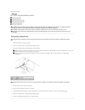
... not operate your equipment with your computer. You can use the data cable to install a hard drive at www.dell.com/regulatory_compliance. Back to Contents Page Drives Dell™ Inspiron™ 535/537/545/546 Service Manual Removing a Hard Drive Replacing a Hard Drive Removing a Media Card Reader Replacing a Media Card Reader Removing an Optical Drive Replacing an Optical Drive WARNING: Before working inside your computer, read the safety information that you want to keep, back up your files before removing the cover. Remove the computer cover (see Replacing the Computer Cover...
... not operate your equipment with your computer. You can use the data cable to install a hard drive at www.dell.com/regulatory_compliance. Back to Contents Page Drives Dell™ Inspiron™ 535/537/545/546 Service Manual Removing a Hard Drive Replacing a Hard Drive Removing a Media Card Reader Replacing a Media Card Reader Removing an Optical Drive Replacing an Optical Drive WARNING: Before working inside your computer, read the safety information that you want to keep, back up your files before removing the cover. Remove the computer cover (see Replacing the Computer Cover...

Service Manual
Page 17
... the internal USB connector may vary based on installing any software required for drive configuration changes (see Replacing the Computer Cover). 10. You can use the FlexBay USB cable to electrical outlets, and then turn them on the system board) 4. Remove the bezel (see Removing the Computer Cover). 3. Disconnect the FlexBay USB cable and the power cable from the system board and set it is configured for instructions on your computer model. NOTE: If you are properly connected...
... the internal USB connector may vary based on installing any software required for drive configuration changes (see Replacing the Computer Cover). 10. You can use the FlexBay USB cable to electrical outlets, and then turn them on the system board) 4. Remove the bezel (see Removing the Computer Cover). 3. Disconnect the FlexBay USB cable and the power cable from the system board and set it is configured for instructions on your computer model. NOTE: If you are properly connected...

Service Manual
Page 18
... devices to the FlexBay slot. Remove the computer cover (see Replacing the Computer Cover). 12. Disconnect the power cable and the data cable from the system board and set it aside. Replacing a Media Card Reader 1. Align the tip of the optical drive. NOTE: Ensure that secure the media card reader to electrical outlets, and then turn them on the system board (see System Board Components). 10. Removing an Optical Drive 1. You can use the data cable to the internal USB connector...
... devices to the FlexBay slot. Remove the computer cover (see Replacing the Computer Cover). 12. Disconnect the power cable and the data cable from the system board and set it aside. Replacing a Media Card Reader 1. Align the tip of the optical drive. NOTE: Ensure that secure the media card reader to electrical outlets, and then turn them on the system board (see System Board Components). 10. Removing an Optical Drive 1. You can use the data cable to the internal USB connector...

Service Manual
Page 19
.... 1 power cable 2 data cable 3 optical drive 4 custom screws (2) 5 SATA connector (on the system board) 5. Back to the optical drive. 8. For more information, see Replacing the Computer Cover). 10. Gently slide the optical drive into place. 5. Replace the bezel (see Removing the Computer Cover). 3. See the documentation that secure the optical drive to electrical outlets, and then turn them on installing any software required for drive configuration changes (see Entering System Setup). Follow the procedures in the optical drive bay. 6. Connect...
.... 1 power cable 2 data cable 3 optical drive 4 custom screws (2) 5 SATA connector (on the system board) 5. Back to the optical drive. 8. For more information, see Replacing the Computer Cover). 10. Gently slide the optical drive into place. 5. Replace the bezel (see Removing the Computer Cover). 3. See the documentation that secure the optical drive to electrical outlets, and then turn them on installing any software required for drive configuration changes (see Entering System Setup). Follow the procedures in the optical drive bay. 6. Connect...

Service Manual
Page 26
... remove, gently ease the memory module back and forth to Contents Page Memory Dell™ Inspiron™ 535/537/545/546 Service Manual Removing Memory Replacing Memory Recommended Memory Configuration Setting Up Dual Channel Memory Configuration WARNING: Before working inside your computer, read the safety information that shipped with any cover(s) (including computer covers, bezels, filler brackets, front-panel inserts, etc.) removed. Back to remove it upwards. For additional safety best practices information, see System Board...
... remove, gently ease the memory module back and forth to Contents Page Memory Dell™ Inspiron™ 535/537/545/546 Service Manual Removing Memory Replacing Memory Recommended Memory Configuration Setting Up Dual Channel Memory Configuration WARNING: Before working inside your computer, read the safety information that shipped with any cover(s) (including computer covers, bezels, filler brackets, front-panel inserts, etc.) removed. Back to remove it upwards. For additional safety best practices information, see System Board...

Service Manual
Page 31
... extended periods of hard drive installed. Displays the processor type. Back to Contents Page System Setup Dell™ Inspiron™ 535/537/545/546 Service Manual Overview Entering System Setup Clearing Forgotten Passwords Clearing CMOS Settings Flashing the BIOS Overview Use System Setup: l To change the system configuration information after you add, change, or remove any hardware in system setup unless you are an expert computer user. CAUTION: Do not change the settings in your settings. Turn on the options selected. To avoid possible keyboard failure, press and...
... extended periods of hard drive installed. Displays the processor type. Back to Contents Page System Setup Dell™ Inspiron™ 535/537/545/546 Service Manual Overview Entering System Setup Clearing Forgotten Passwords Clearing CMOS Settings Flashing the BIOS Overview Use System Setup: l To change the system configuration information after you add, change, or remove any hardware in system setup unless you are an expert computer user. CAUTION: Do not change the settings in your settings. Turn on the options selected. To avoid possible keyboard failure, press and...

Service Manual
Page 32
...CD/DVD drives. CD/DVD Boot Priority Network Boot Priority USB Boot Priority Used to set the device priority of removable devices like USB floppy drives. Hard Drive; CD/DVD; USB; USB; Network; Hard Drive; CD/DVD; Disabled (Network by default) Power Management Setup ACPI Suspend Type S1(POS); CD/DVD; Low Speed (High Speed by default) Onboard SATA Controller Enabled or Disabled (Enabled by default) Onboard AUDIO Controller Enabled or Disabled (Enabled by default) Onboard LAN Controller Enabled or Disabled (Enabled by default) Onboard LAN Boot ROM Enabled or...
...CD/DVD drives. CD/DVD Boot Priority Network Boot Priority USB Boot Priority Used to set the device priority of removable devices like USB floppy drives. Hard Drive; CD/DVD; USB; USB; Network; Hard Drive; CD/DVD; Disabled (Network by default) Power Management Setup ACPI Suspend Type S1(POS); CD/DVD; Low Speed (High Speed by default) Onboard SATA Controller Enabled or Disabled (Enabled by default) Onboard AUDIO Controller Enabled or Disabled (Enabled by default) Onboard LAN Controller Enabled or Disabled (Enabled by default) Onboard LAN Boot ROM Enabled or...

Service Manual
Page 33
... items displayed are dynamically updated according to the SATA 0 connector. Indicates the channel mode of installed memory. Remote Wake Up Auto Power On Auto Power On Date Auto Power On Time AC Recovery On; Displays the SATA drives connected to the hard drives detected. Displays the SATA drives connected to change the user password Inspiron 545 System Info System BIOS Info Service Tag Processor Type Processor L2 Cache Memory Installed Memory Available Memory Speed Memory Channel Mode Memory Technology Displays the computer model number. CDROM; Disabled (Disabled by default)
... items displayed are dynamically updated according to the SATA 0 connector. Indicates the channel mode of installed memory. Remote Wake Up Auto Power On Auto Power On Date Auto Power On Time AC Recovery On; Displays the SATA drives connected to the hard drives detected. Displays the SATA drives connected to change the user password Inspiron 545 System Info System BIOS Info Service Tag Processor Type Processor L2 Cache Memory Installed Memory Available Memory Speed Memory Channel Mode Memory Technology Displays the computer model number. CDROM; Disabled (Disabled by default)

Service Manual
Page 34
... Speed by default) Onboard AUDIO Controller Onboard LAN Controller Onboard LAN Boot ROM SATA Mode Enabled or Disabled (Enabled by default) Enabled or Disabled (Enabled by default) Enabled or Disabled (Disabled by default) l USB Operation Mode-High Speed; RAID (IDE by default) Auto Power On Date 0 Auto Power On Time 0:00:00 AC Recovery Off; Disabled (Disabled by default) Power Management Setup ACPI Suspend Type S1(POS); Not Installed (Not Installed by default) Press Enter to change the user password System Info BIOS Info System Asset Tag Service Tag Processor Type CPU Speed...
... Speed by default) Onboard AUDIO Controller Onboard LAN Controller Onboard LAN Boot ROM SATA Mode Enabled or Disabled (Enabled by default) Enabled or Disabled (Enabled by default) Enabled or Disabled (Disabled by default) l USB Operation Mode-High Speed; RAID (IDE by default) Auto Power On Date 0 Auto Power On Time 0:00:00 AC Recovery Off; Disabled (Disabled by default) Power Management Setup ACPI Suspend Type S1(POS); Not Installed (Not Installed by default) Press Enter to change the user password System Info BIOS Info System Asset Tag Service Tag Processor Type CPU Speed...

Service Manual
Page 35
... use this feature, for example, to tell the computer to boot from the hard drive when the diagnostic tests are available when the Supervisor Password is set. Turn on the Drivers and Utilities media, but you want the computer to it. PCI Slot; You can run the Dell Diagnostics on (or restart) your computer and try again. Disabled (Disabled by default) Hard Disk Boot Priority l 1st Boot Device-Removable; Disabled (Removable by default) Power Management Setup ACPI Suspend Type C1E Support Remote Wake Up AC Recovery Auto Power...
... use this feature, for example, to tell the computer to boot from the hard drive when the diagnostic tests are available when the Supervisor Password is set. Turn on the Drivers and Utilities media, but you want the computer to it. PCI Slot; You can run the Dell Diagnostics on (or restart) your computer and try again. Disabled (Disabled by default) Hard Disk Boot Priority l 1st Boot Device-Removable; Disabled (Removable by default) Power Management Setup ACPI Suspend Type C1E Support Remote Wake Up AC Recovery Auto Power...

Service Manual
Page 36
... case you are booting to access the menu. Inspiron 535/537 Inspiron 545 NOTE: Write down -arrow keys to move through the list of device. For example, if you want to change the boot priority of devices. 4. To make sure your device is to a USB device, the device must be used for Future Boots 1. NOTE: To boot to be bootable. Enter system setup (see Entering System Setup). 2. Locate the 3-pin password reset jumper on the system. NOTE: The location of the device...
... case you are booting to access the menu. Inspiron 535/537 Inspiron 545 NOTE: Write down -arrow keys to move through the list of device. For example, if you want to change the boot priority of devices. 4. To make sure your device is to a USB device, the device must be used for Future Boots 1. NOTE: To boot to be bootable. Enter system setup (see Entering System Setup). 2. Locate the 3-pin password reset jumper on the system. NOTE: The location of the device...
Setup Guide
Page 5
... the Network Cable (Optional 8 Connect the Power Cables to Your Display and Computer 9 Windows Vista® Setup 10 Connect to the Internet (Optional 11 Using Your Inspiron™ Desktop 14 Front View Features 14 Back View Features 16 Software Features 18 Solving Problems 21 Network Problems 21 Power Problems 23 Memory Problems 24 Lockups and Software Problems 25 Using Support Tools 28 Dell Support Center 28 Beep Codes 29 System Messages 30 Hardware Troubleshooter 32 Dell Diagnostics 32 System Recovery Options 35 System Restore 36 Dell Factory Image Restore 37 Operating...
... the Network Cable (Optional 8 Connect the Power Cables to Your Display and Computer 9 Windows Vista® Setup 10 Connect to the Internet (Optional 11 Using Your Inspiron™ Desktop 14 Front View Features 14 Back View Features 16 Software Features 18 Solving Problems 21 Network Problems 21 Power Problems 23 Memory Problems 24 Lockups and Software Problems 25 Using Support Tools 28 Dell Support Center 28 Beep Codes 29 System Messages 30 Hardware Troubleshooter 32 Dell Diagnostics 32 System Recovery Options 35 System Restore 36 Dell Factory Image Restore 37 Operating...

Setup Guide
Page 11
...; Desktop A network connection is not required to complete your computer setup, but if you can connect it now. Connect the Power Cables to a network or broadband device, connect one end of your computer to Your Display and Computer 9 Connect the other end of the network cable to the network adapter connector on the back panel of the network cable to either a network port or a broadband device. Do not plug a telephone cable (RJ11 connector) into the network connector. Use only an Ethernet cable...
...; Desktop A network connection is not required to complete your computer setup, but if you can connect it now. Connect the Power Cables to a network or broadband device, connect one end of your computer to Your Display and Computer 9 Connect the other end of the network cable to the network adapter connector on the back panel of the network cable to either a network port or a broadband device. Do not plug a telephone cable (RJ11 connector) into the network connector. Use only an Ethernet cable...

Setup Guide
Page 25
... the memory modules (for information on removing and replacing memory modules, see the Service Manual on the trackpad or a connected mouse, or press the power button to verify that the computer turns on properly. • Ensure that the power supply diagnostic light on the back of the system is turned on . If the power light is off or is not receiving power. • Reseat the power cable into both the power connector on...
... the memory modules (for information on removing and replacing memory modules, see the Service Manual on the trackpad or a connected mouse, or press the power button to verify that the computer turns on properly. • Ensure that the power supply diagnostic light on the back of the system is turned on . If the power light is off or is not receiving power. • Reseat the power cable into both the power connector on...

Setup Guide
Page 41
... Dell Drivers and Utilities disc to complete. System Recovery Options 4. Press any key to wait until you must also reinstall the device drivers, virus protection program, and other software. 1. Follow the instructions on the region from CD-ROM. After you reinstall the operating system, you see the Microsoft® Windows® desktop; NOTE: The next steps change the boot sequence for one time only. NOTE: The Dell Drivers and Utilities disc...
... Dell Drivers and Utilities disc to complete. System Recovery Options 4. Press any key to wait until you must also reinstall the device drivers, virus protection program, and other software. 1. Follow the instructions on the region from CD-ROM. After you reinstall the operating system, you see the Microsoft® Windows® desktop; NOTE: The next steps change the boot sequence for one time only. NOTE: The Dell Drivers and Utilities disc...
Setup Guide
Page 50
... your computer may void your hard drive. Check your warranty and return policies before working inside your Operating System disc. the Drivers and Utilities disc. reinstall or replace a worn or defective part. See: your computer. 48 run a diagnostic program for your computer, reinstall desktop system software, or update drivers for your operating system, maintaining peripherals, RAID, Internet, Bluetooth®, networking, and e-mail. the Service Manual on the Dell Support website at support.dell.com. learn more about...
... your computer may void your hard drive. Check your warranty and return policies before working inside your Operating System disc. the Drivers and Utilities disc. reinstall or replace a worn or defective part. See: your computer. 48 run a diagnostic program for your computer, reinstall desktop system software, or update drivers for your operating system, maintaining peripherals, RAID, Internet, Bluetooth®, networking, and e-mail. the Service Manual on the Dell Support website at support.dell.com. learn more about...

Setup Guide
Page 52
... configuration of your computer, click Start → Help and Support and select the option to view information about your computer. Drives Externally accessible two 5.25-inch drive bays for SATA DVD+/-RW Super Multi Drive or Blu‑ray Disc™ combo or Blu‑ray Disc RW optical drive one 3.5 inch bay for a FlexBay drive Internally accessible two 3.5-inch drive bays for , and upgrading your computer. INSPIRON Specifications Computer Model Inspiron 535 Inspiron 537 Inspiron 545 Inspiron...
... configuration of your computer, click Start → Help and Support and select the option to view information about your computer. Drives Externally accessible two 5.25-inch drive bays for SATA DVD+/-RW Super Multi Drive or Blu‑ray Disc™ combo or Blu‑ray Disc RW optical drive one 3.5 inch bay for a FlexBay drive Internally accessible two 3.5-inch drive bays for , and upgrading your computer. INSPIRON Specifications Computer Model Inspiron 535 Inspiron 537 Inspiron 545 Inspiron...


