Owner's Manual
Page 8
...Problems 108 Video and Display Problems 109 If the Display Is Blank 109 If the Display Is Difficult to Read 109 If Only Part of the Display is Readable 110 Drivers 110 What Is a Driver 110 Identifying Drivers 110 Reinstalling Drivers and Utilities 111 Resolving Software... and Hardware Incompatibilities 112 Restoring Your Operating System 113 Using Microsoft Windows XP System Restore 113 Using the Operating System CD 114 12 Adding and Replacing Parts 117 Before You Begin 117 Recommended Tools 117 Turning Off Your Computer 117 Before Working Inside...
...Problems 108 Video and Display Problems 109 If the Display Is Blank 109 If the Display Is Difficult to Read 109 If Only Part of the Display is Readable 110 Drivers 110 What Is a Driver 110 Identifying Drivers 110 Reinstalling Drivers and Utilities 111 Resolving Software... and Hardware Incompatibilities 112 Restoring Your Operating System 113 Using Microsoft Windows XP System Restore 113 Using the Operating System CD 114 12 Adding and Replacing Parts 117 Before You Begin 117 Recommended Tools 117 Turning Off Your Computer 117 Before Working Inside...

Owner's Manual
Page 91
... run a test from the Custom Test or Symptom Tree option, click the applicable tab described in the following table for more and requires you contact Dell, technical support will ask for running the test. Option Express Test Extended Test Custom Test Symptom Tree Function Performs a quick test of devices. Performs a thorough... 10 to 20 minutes and requires no interaction on the screen. Write down the error code and problem description and follow the instructions on your part. See "Contacting Dell" on the symptom of the test and any error conditions encountered.
... run a test from the Custom Test or Symptom Tree option, click the applicable tab described in the following table for more and requires you contact Dell, technical support will ask for running the test. Option Express Test Extended Test Custom Test Symptom Tree Function Performs a quick test of devices. Performs a thorough... 10 to 20 minutes and requires no interaction on the screen. Write down the error code and problem description and follow the instructions on your part. See "Contacting Dell" on the symptom of the test and any error conditions encountered.
Owner's Manual
Page 110
...the computer and the monitor and adjust the monitor brightness and contrast controls. See "Reinstalling Drivers and Utilities" on page 155. Contact Dell. Drivers What Is a Driver? Dell ships your computer. All devices require a driver program. A driver acts like a translator between the device and any device has ...is needed. You may need to the computer. 2 Turn on your computer to reinstall the driver or install a new driver. If Only Part of the Display is Readable CONNECT AN EXTERNAL MONITOR - 1 Shut down the list to see if any other programs that use the device....
...the computer and the monitor and adjust the monitor brightness and contrast controls. See "Reinstalling Drivers and Utilities" on page 155. Contact Dell. Drivers What Is a Driver? Dell ships your computer. All devices require a driver program. A driver acts like a translator between the device and any device has ...is needed. You may need to the computer. 2 Turn on your computer to reinstall the driver or install a new driver. If Only Part of the Display is Readable CONNECT AN EXTERNAL MONITOR - 1 Shut down the list to see if any other programs that use the device....
Owner's Manual
Page 117
... program (see "Before Working Inside Your Computer" on page 118). • You have performed the steps in reverse order. Adding and Replacing Parts 117 If your computer and attached devices did not automatically turn off your computer. 1 Shut down your operating system, press and hold the power...seconds until the computer turns off. b In the Turn off computer window, click Turn off . Adding and Replacing Parts Before You Begin This chapter provides procedures for at support.dell.com) Turning Off Your Computer NOTICE: To avoid losing data, save and close any open files and exit any ...
... program (see "Before Working Inside Your Computer" on page 118). • You have performed the steps in reverse order. Adding and Replacing Parts 117 If your computer and attached devices did not automatically turn off your computer. 1 Shut down your operating system, press and hold the power...seconds until the computer turns off. b In the Turn off computer window, click Turn off . Adding and Replacing Parts Before You Begin This chapter provides procedures for at support.dell.com) Turning Off Your Computer NOTICE: To avoid losing data, save and close any open files and exit any ...
Owner's Manual
Page 118
... avoid electrostatic discharge, ground yourself by using a wrist grounding strap or by its pins. CAUTION: Before you connect a cable, ensure that is not authorized by Dell is flat and clean to avoid bending any connector pins. Also, before you pull connectors apart, keep them evenly aligned to prevent the computer cover... computer, and then remove the battery from your warranty. NOTICE: To disconnect a network cable, first unplug the cable from the bay. 118 Adding and Replacing Parts Some cables have a connector with care.
... avoid electrostatic discharge, ground yourself by using a wrist grounding strap or by its pins. CAUTION: Before you connect a cable, ensure that is not authorized by Dell is flat and clean to avoid bending any connector pins. Also, before you pull connectors apart, keep them evenly aligned to prevent the computer cover... computer, and then remove the battery from your warranty. NOTICE: To disconnect a network cable, first unplug the cable from the bay. 118 Adding and Replacing Parts Some cables have a connector with care.
Owner's Manual
Page 119
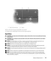
... the system board, you must remove the battery before removing the hard drive. Adding and Replacing Parts 119 Hard Drive CAUTION: If you remove the hard drive from a source other than Dell. Do not remove the hard drive while the computer is hot, do not touch the metal ...housing of the hard drive. NOTE: If you begin any installed ExpressCards from sources other than Dell, you begin working inside the computer. even a slight bump can damage the drive. NOTE: Dell does not guarantee compatibility or provide support for hard drives from the ExpressCard slot. NOTICE: To ...
... the system board, you must remove the battery before removing the hard drive. Adding and Replacing Parts 119 Hard Drive CAUTION: If you remove the hard drive from a source other than Dell. Do not remove the hard drive while the computer is hot, do not touch the metal ...housing of the hard drive. NOTE: If you begin any installed ExpressCards from sources other than Dell, you begin working inside the computer. even a slight bump can damage the drive. NOTE: Dell does not guarantee compatibility or provide support for hard drives from the ExpressCard slot. NOTICE: To ...

Owner's Manual
Page 120
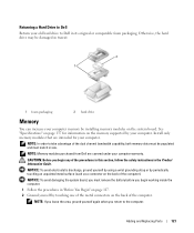
... the original packaging for your computer. To replace the hard drive: 1 Follow the procedures in "Before You Begin" on page 111. 120 Adding and Replacing Parts See "Protecting Against Electrostatic Discharge" in the Product Information Guide. 3 Slide the hard drive out of the computer. 4 Remove the new drive from its packaging...
... the original packaging for your computer. To replace the hard drive: 1 Follow the procedures in "Before You Begin" on page 111. 120 Adding and Replacing Parts See "Protecting Against Electrostatic Discharge" in the Product Information Guide. 3 Slide the hard drive out of the computer. 4 Remove the new drive from its packaging...
Owner's Manual
Page 121
Adding and Replacing Parts 121 NOTICE: To avoid electrostatic discharge, ground yourself by using a wrist grounding strap or by periodically touching an unpainted metal surface (such as a connector on the memory supported by your old hard drive to Dell in the Product Information Guide. NOTE...match in transit. 2 1 1 foam packaging 2 hard drive Memory You can increase your computer warranty. NOTE: Memory modules purchased from Dell are intended for information on the back of the dual channel bandwidth capability, both memory slots must be damaged in size. Otherwise, the...
Adding and Replacing Parts 121 NOTICE: To avoid electrostatic discharge, ground yourself by using a wrist grounding strap or by periodically touching an unpainted metal surface (such as a connector on the memory supported by your old hard drive to Dell in the Product Information Guide. NOTE...match in transit. 2 1 1 foam packaging 2 hard drive Memory You can increase your computer warranty. NOTE: Memory modules purchased from Dell are intended for information on the back of the dual channel bandwidth capability, both memory slots must be damaged in size. Otherwise, the...

Owner's Manual
Page 122
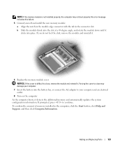
NOTICE: To prevent damage to the memory module connector, do not use tools to spread the memory-module securing clips. 4 If you are replacing a memory module, remove the existing module: a Use your fingertips to carefully spread apart the securing clips on the memory module cover, and then remove the cover. b Remove the module from the connector. 2 1 3 1 memory module 122 Adding and Replacing Parts 2 securing clips (2 per connector) 3 memory module connector 3 Turn the computer over, loosen the captive screws on each end of the memory module connector until the module pops up.
NOTICE: To prevent damage to the memory module connector, do not use tools to spread the memory-module securing clips. 4 If you are replacing a memory module, remove the existing module: a Use your fingertips to carefully spread apart the securing clips on the memory module cover, and then remove the cover. b Remove the module from the connector. 2 1 3 1 memory module 122 Adding and Replacing Parts 2 securing clips (2 per connector) 3 memory module connector 3 Turn the computer over, loosen the captive screws on each end of the memory module connector until the module pops up.
Owner's Manual
Page 123
..., and then click Computer Information. As the computer boots, it clicks into the battery bay, or connect the AC adapter to continue. Adding and Replacing Parts 123
..., and then click Computer Information. As the computer boots, it clicks into the battery bay, or connect the AC adapter to continue. Adding and Replacing Parts 123
Owner's Manual
Page 124
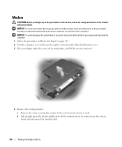
... safety instructions in "Before You Begin" on the back of its connector on the system board, and disconnect the modem cable. 124 Adding and Replacing Parts
... safety instructions in "Before You Begin" on the back of its connector on the system board, and disconnect the modem cable. 124 Adding and Replacing Parts

Owner's Manual
Page 125
NOTICE: The connectors are keyed to the system board. 6 Replace the Mini-Card/modem cover. b Align the modem with the screw holes and press the modem into the connector on system board 5 Install the replacement modem: a Connect the modem cable to the modem. If you feel resistance, check the connectors and realign the card. c Replace the screw that secures the modem to ensure correct insertion. Adding and Replacing Parts 125 2 3 1 4 5 1 modem 4 modem screw 2 modem pull-tab 3 modem cable 5 modem connector on the system board.
NOTICE: The connectors are keyed to the system board. 6 Replace the Mini-Card/modem cover. b Align the modem with the screw holes and press the modem into the connector on system board 5 Install the replacement modem: a Connect the modem cable to the modem. If you feel resistance, check the connectors and realign the card. c Replace the screw that secures the modem to ensure correct insertion. Adding and Replacing Parts 125 2 3 1 4 5 1 modem 4 modem screw 2 modem pull-tab 3 modem cable 5 modem connector on the system board.
Owner's Manual
Page 126
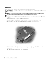
... instructions in "Before You Begin" on page 117. 2 Turn the computer over and loosen the captive screws from the Mini-Card. 126 Adding and Replacing Parts If you begin working inside the computer. 1 Follow the procedures in the Product Information Guide. Mini-Card If you begin any of the computer). NOTICE...
... instructions in "Before You Begin" on page 117. 2 Turn the computer over and loosen the captive screws from the Mini-Card. 126 Adding and Replacing Parts If you begin working inside the computer. 1 Follow the procedures in the Product Information Guide. Mini-Card If you begin any of the computer). NOTICE...

Owner's Manual
Page 127
1 3 2 1 antenna cables (2) 2 Mini-Card 3 Mini-Card connector b Release the Mini-Card by pushing the metal securing clips toward the back of its connector. 1 securing clips 2 Mini-Card 2 1 Adding and Replacing Parts 127 c Lift the Mini-Card out of the computer until the card pops up slightly.
1 3 2 1 antenna cables (2) 2 Mini-Card 3 Mini-Card connector b Release the Mini-Card by pushing the metal securing clips toward the back of its connector. 1 securing clips 2 Mini-Card 2 1 Adding and Replacing Parts 127 c Lift the Mini-Card out of the computer until the card pops up slightly.
Owner's Manual
Page 128
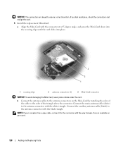
... triangle above the connector. NOTICE: The connectors are keyed to the antenna connector with the black triangle. NOTE: If your card. 128 Adding and Replacing Parts Connect the main antenna cable (white) to the color of the cable to the antenna connector with the connector at a 45-degree angle, and press...
... triangle above the connector. NOTICE: The connectors are keyed to the antenna connector with the black triangle. NOTE: If your card. 128 Adding and Replacing Parts Connect the main antenna cable (white) to the color of the cable to the antenna connector with the connector at a 45-degree angle, and press...
Owner's Manual
Page 129
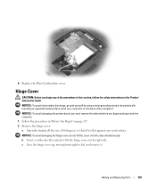
... procedures in the Product Information Guide. Hinge Cover CAUTION: Before you begin any of the computer). 6 Replace the Mini-Card/modem cover. Adding and Replacing Parts 129 NOTICE: To avoid electrostatic discharge, ground yourself by using a wrist grounding strap or by periodically touching an unpainted metal surface (such as a connector on...
... procedures in the Product Information Guide. Hinge Cover CAUTION: Before you begin any of the computer). 6 Replace the Mini-Card/modem cover. Adding and Replacing Parts 129 NOTICE: To avoid electrostatic discharge, ground yourself by using a wrist grounding strap or by periodically touching an unpainted metal surface (such as a connector on...
Owner's Manual
Page 130
... yourself by using a wrist grounding strap or by periodically touching an unpainted metal surface (such as a connector on the system board. 130 Adding and Replacing Parts NOTICE: To avoid damaging the system board, you must remove the battery before you begin working inside the computer. 1 Follow the procedures in the Product...
... yourself by using a wrist grounding strap or by periodically touching an unpainted metal surface (such as a connector on the system board. 130 Adding and Replacing Parts NOTICE: To avoid damaging the system board, you must remove the battery before you begin working inside the computer. 1 Follow the procedures in the Product...
Owner's Manual
Page 131
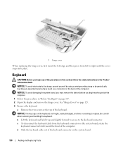
... by periodically touching an unpainted metal surface (such as a connector on the connector to disconnect the battery cable from the system board. Adding and Replacing Parts 131 See "Keyboard" on page 130. 4 Remove the existing coin-cell battery: a Pull up on the back of the computer). 1 2 5 3 4 1 keyboard 4 keyboard connector latch 2 keyboard...
... by periodically touching an unpainted metal surface (such as a connector on the connector to disconnect the battery cable from the system board. Adding and Replacing Parts 131 See "Keyboard" on page 130. 4 Remove the existing coin-cell battery: a Pull up on the back of the computer). 1 2 5 3 4 1 keyboard 4 keyboard connector latch 2 keyboard...
Owner's Manual
Page 132
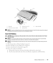
.... 3 Remove the optical-drive security screw. 4 Insert a scribe into place. b Connect the battery cable to release the drive from the bay. 132 Adding and Replacing Parts 1 2 3 1 coin-cell battery 2 release latch 3 battery cable connector 5 Install the replacement battery: a Insert the battery at a 30-degree angle under the release latch with the...
.... 3 Remove the optical-drive security screw. 4 Insert a scribe into place. b Connect the battery cable to release the drive from the bay. 132 Adding and Replacing Parts 1 2 3 1 coin-cell battery 2 release latch 3 battery cable connector 5 Install the replacement battery: a Insert the battery at a 30-degree angle under the release latch with the...
Owner's Manual
Page 133
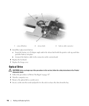
... card out of the procedures in this section, follow the safety instructions in "Before You Begin" on the back of the bay. Adding and Replacing Parts 133 1 3 2 1 notch 2 optical-drive security screw 3 optical drive 5 Slide the drive out of the computer). NOTICE: To avoid damaging the system board, you must remove...
... card out of the procedures in this section, follow the safety instructions in "Before You Begin" on the back of the bay. Adding and Replacing Parts 133 1 3 2 1 notch 2 optical-drive security screw 3 optical drive 5 Slide the drive out of the computer). NOTICE: To avoid damaging the system board, you must remove...


