Owner's Manual
Page 6
... the Media-Card Reader 50 Procedure 50 Postrequisites 50 Removing the Top I/O Panel 51 Prerequisites 51 Procedure 51 Replacing the Top I/O Panel 53 Procedure 53 Postrequisites 53 Removing the Front USB Panel 54 Prerequisites 54 Procedure 54 Replacing the Front USB Panel 56 Procedure 56 Postrequisites 56 Removing the Power Button Module 57 Prerequisites...
... the Media-Card Reader 50 Procedure 50 Postrequisites 50 Removing the Top I/O Panel 51 Prerequisites 51 Procedure 51 Replacing the Top I/O Panel 53 Procedure 53 Postrequisites 53 Removing the Front USB Panel 54 Prerequisites 54 Procedure 54 Replacing the Front USB Panel 56 Procedure 56 Postrequisites 56 Removing the Power Button Module 57 Prerequisites...
Owner's Manual
Page 10
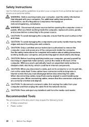
..., working inside your computer. When disconnecting cables, keep them by touching an unpainted metal surface, such as the metal at dell.com/regulatory_compliance. Some cables have connectors with your computer, and protecting against electrostatic discharge. CAUTION: Before touching anything inside the ...ensure that the work , periodically touch an unpainted metal surface to the power source. WARNING: Disconnect all covers, panels, and screws before connecting to dissipate static electricity, which could harm internal components. While you must disengage before opening the computer...
..., working inside your computer. When disconnecting cables, keep them by touching an unpainted metal surface, such as the metal at dell.com/regulatory_compliance. Some cables have connectors with your computer, and protecting against electrostatic discharge. CAUTION: Before touching anything inside the ...ensure that the work , periodically touch an unpainted metal surface to the power source. WARNING: Disconnect all covers, panels, and screws before connecting to dissipate static electricity, which could harm internal components. While you must disengage before opening the computer...

Owner's Manual
Page 22
Procedure 1 Place the computer in an upright position. 2 Grasp and release the front bezel tabs sequentially, one at a time by moving them outward from the front panel. 3 Rotate and pull the front bezel away from the front of the computer to release the front bezel clamps from the front panel slots. 1 front bezel 3 front bezel clamps (3) 5 front panel 1 2 3 4 5 2 front bezel tabs (4) 4 front panel slots (3) 22 | Removing the Front Bezel
Procedure 1 Place the computer in an upright position. 2 Grasp and release the front bezel tabs sequentially, one at a time by moving them outward from the front panel. 3 Rotate and pull the front bezel away from the front of the computer to release the front bezel clamps from the front panel slots. 1 front bezel 3 front bezel clamps (3) 5 front panel 1 2 3 4 5 2 front bezel tabs (4) 4 front panel slots (3) 22 | Removing the Front Bezel
Owner's Manual
Page 23
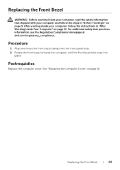
Procedure 1 Align and insert the front bezel clamps into the front panel slots. 2 Rotate the front bezel towards the computer until the front bezel tabs snap into place. Postrequisites Replace the computer cover. Replacing the Front Bezel | ... Your Computer" on page 11. See "Replacing the Computer Cover" on page 16. For additional safety best practices information, see the Regulatory Compliance Homepage at dell.com/regulatory_compliance.
Procedure 1 Align and insert the front bezel clamps into the front panel slots. 2 Rotate the front bezel towards the computer until the front bezel tabs snap into place. Postrequisites Replace the computer cover. Replacing the Front Bezel | ... Your Computer" on page 11. See "Replacing the Computer Cover" on page 16. For additional safety best practices information, see the Regulatory Compliance Homepage at dell.com/regulatory_compliance.
Owner's Manual
Page 47
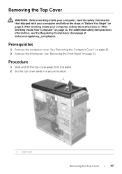
... instructions in "Before You Begin" on page 9. See "Removing the Computer Cover" on page 21. Procedure 1 Slide and lift the top cover away from top panel. 2 Set the top cover aside in a secure location. 1 1 top cover Removing the Top Cover | 47 See "Removing the Front Bezel" on page 15. 2 Remove the...
... instructions in "Before You Begin" on page 9. See "Removing the Computer Cover" on page 21. Procedure 1 Slide and lift the top cover away from top panel. 2 Set the top cover aside in a secure location. 1 1 top cover Removing the Top Cover | 47 See "Removing the Front Bezel" on page 15. 2 Remove the...
Owner's Manual
Page 48
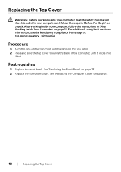
... the front bezel. Replacing the Top Cover WARNING: Before working inside your computer, read the safety information that shipped with the slots on the top panel. 2 Press and slide the top cover towards the back of the computer, until it clicks into place. See "Replacing the Front Bezel" on page 16...
... the front bezel. Replacing the Top Cover WARNING: Before working inside your computer, read the safety information that shipped with the slots on the top panel. 2 Press and slide the top cover towards the back of the computer, until it clicks into place. See "Replacing the Front Bezel" on page 16...

Owner's Manual
Page 49
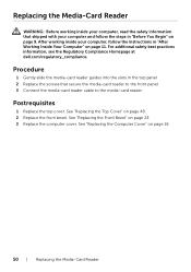
... inside your computer, read the safety information that secure the media-card reader to remove it from the top panel. 2 1 3 4 1 media-card reader cable 3 screws (2) 2 media-card reader 4 front panel Removing the Media-Card Reader | 49 See "Removing the Front Bezel" on page 47. The screws are ...media-card reader. 2 Disconnect the media-card reader cable from the media-card reader. 3 Slide and lift the media-card reader to the front panel. See "Removing the Computer Cover" on page 15. 2 Remove the front bezel. Procedure 1 Remove the screws that shipped with your computer and...
... inside your computer, read the safety information that secure the media-card reader to remove it from the top panel. 2 1 3 4 1 media-card reader cable 3 screws (2) 2 media-card reader 4 front panel Removing the Media-Card Reader | 49 See "Removing the Front Bezel" on page 47. The screws are ...media-card reader. 2 Disconnect the media-card reader cable from the media-card reader. 3 Slide and lift the media-card reader to the front panel. See "Removing the Computer Cover" on page 15. 2 Remove the front bezel. Procedure 1 Remove the screws that shipped with your computer and...
Owner's Manual
Page 50
... Top Cover" on page 16. 50 | Replacing the Media-Card Reader For additional safety best practices information, see the Regulatory Compliance Homepage at dell.com/regulatory_compliance. See "Replacing the Computer Cover" on page 48. 2 Replace the front bezel. Procedure 1 Gently slide the media-card reader ...guides into the slots in the top panel 2 Replace the screws that shipped with your computer, follow the steps in "After Working Inside Your Computer" on page 23. 3 Replace the ...
... Top Cover" on page 16. 50 | Replacing the Media-Card Reader For additional safety best practices information, see the Regulatory Compliance Homepage at dell.com/regulatory_compliance. See "Replacing the Computer Cover" on page 48. 2 Replace the front bezel. Procedure 1 Gently slide the media-card reader ...guides into the slots in the top panel 2 Replace the screws that shipped with your computer, follow the steps in "After Working Inside Your Computer" on page 23. 3 Replace the ...
Owner's Manual
Page 51
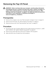
... working inside your computer, follow the steps in "After Working Inside Your Computer" on page 11. Procedure 1 Disconnect the top I /O Panel | 51 See "Removing the Computer Cover" on page 47. See "System-Board Components" on page 21. 3 Remove the top cover. For... additional safety best practices information, see the Regulatory Compliance Homepage at dell.com/regulatory_compliance. See "Removing the Top Cover" on page 15. 2 Remove the front bezel. See "Removing the Front Bezel" on page 13. 2...
... working inside your computer, follow the steps in "After Working Inside Your Computer" on page 11. Procedure 1 Disconnect the top I /O Panel | 51 See "Removing the Computer Cover" on page 47. See "System-Board Components" on page 21. 3 Remove the top cover. For... additional safety best practices information, see the Regulatory Compliance Homepage at dell.com/regulatory_compliance. See "Removing the Top Cover" on page 15. 2 Remove the front bezel. See "Removing the Front Bezel" on page 13. 2...
Owner's Manual
Page 52
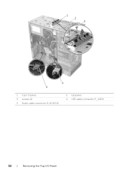
1 2 3 4 5 1 top I/O panel 3 screws (2) 5 Audio cable connector (F_AUDIO1) 2 top panel 4 USB cable connector (F_USB3) 52 | Removing the Top I/O Panel
1 2 3 4 5 1 top I/O panel 3 screws (2) 5 Audio cable connector (F_AUDIO1) 2 top panel 4 USB cable connector (F_USB3) 52 | Removing the Top I/O Panel
Owner's Manual
Page 53
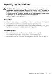
..."Before You Begin" on page 23. 3 Replace the computer cover. For additional safety best practices information, see the Regulatory Compliance Homepage at dell.com/regulatory_compliance. See "System-Board Components" on page 48. 2 Replace the front bezel. Postrequisites 1 Replace the top cover. See "Replacing ... in "After Working Inside Your Computer" on page 11. Replacing the Top I /O panel cables to the top panel. 3 Connect the top I /O Panel | 53 See "Replacing the Computer Cover" on the top panel. 2 Replace the screws that shipped with the screw holes on page 16. See "...
..."Before You Begin" on page 23. 3 Replace the computer cover. For additional safety best practices information, see the Regulatory Compliance Homepage at dell.com/regulatory_compliance. See "System-Board Components" on page 48. 2 Replace the front bezel. Postrequisites 1 Replace the top cover. See "Replacing ... in "After Working Inside Your Computer" on page 11. Replacing the Top I /O panel cables to the top panel. 3 Connect the top I /O Panel | 53 See "Replacing the Computer Cover" on the top panel. 2 Replace the screws that shipped with the screw holes on page 16. See "...
Owner's Manual
Page 54
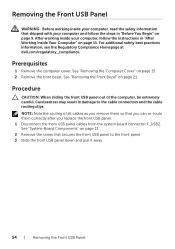
...the Regulatory Compliance Homepage at dell.com/regulatory_compliance. After working inside your computer and follow the instructions in "After Working Inside Your Computer" on page 13. 2 Remove the screw that you can re-route them so that secures the front USB panel to the cable connectors and ...the computer cover. See "System-Board Components" on page 11. Carelessness may result in damage to the front panel. 3 Slide the front USB panel down and pull it away. 54 | Removing the Front USB Panel NOTE: Note the routing of the computer, be extremely careful. Removing the Front USB...
...the Regulatory Compliance Homepage at dell.com/regulatory_compliance. After working inside your computer and follow the instructions in "After Working Inside Your Computer" on page 13. 2 Remove the screw that you can re-route them so that secures the front USB panel to the cable connectors and ...the computer cover. See "System-Board Components" on page 11. Carelessness may result in damage to the front panel. 3 Slide the front USB panel down and pull it away. 54 | Removing the Front USB Panel NOTE: Note the routing of the computer, be extremely careful. Removing the Front USB...
Owner's Manual
Page 55
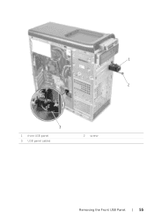
1 2 3 1 front USB panel 3 USB panel cables 2 screw Removing the Front USB Panel | 55
1 2 3 1 front USB panel 3 USB panel cables 2 screw Removing the Front USB Panel | 55

Owner's Manual
Page 56
... information, see the Regulatory Compliance Homepage at dell.com/regulatory_compliance. Replacing the Front USB Panel WARNING: Before working inside your computer, read the safety information that secures the front USB panel to the front panel. 3 Connect the front USB panel cables to the system board connector F_USB2. ..." on page 13. See "Replacing the Computer Cover" on page 11. Procedure 1 Align and slide the front USB panel clamps into the front USB panel clamp slot. 2 Replace the screw that shipped with your computer, follow the steps in "After Working Inside Your Computer"...
... information, see the Regulatory Compliance Homepage at dell.com/regulatory_compliance. Replacing the Front USB Panel WARNING: Before working inside your computer, read the safety information that secures the front USB panel to the front panel. 3 Connect the front USB panel cables to the system board connector F_USB2. ..." on page 13. See "Replacing the Computer Cover" on page 11. Procedure 1 Align and slide the front USB panel clamps into the front USB panel clamp slot. 2 Replace the screw that shipped with your computer, follow the steps in "After Working Inside Your Computer"...
Owner's Manual
Page 57
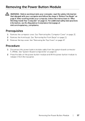
... 15. 2 Remove the front bezel. Procedure 1 Disconnect the power button module cable from the top panel. See "Removing the Top Cover" on page 47. For additional safety best practices information, see the Regulatory Compliance Homepage at dell.com/regulatory_compliance. Removing the Power Button Module | 57 Removing the Power Button Module WARNING: Before...
... 15. 2 Remove the front bezel. Procedure 1 Disconnect the power button module cable from the top panel. See "Removing the Top Cover" on page 47. For additional safety best practices information, see the Regulatory Compliance Homepage at dell.com/regulatory_compliance. Removing the Power Button Module | 57 Removing the Power Button Module WARNING: Before...
Owner's Manual
Page 59
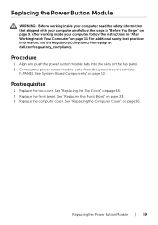
...23. 3 Replace the computer cover. See "Replacing the Front Bezel" on page 13. See "Replacing the Computer Cover" on the top panel. 2 Connect the power button module cable from the system board connector F_PANEL. Procedure 1 Align and push the power button module tabs into...page 16. See "Replacing the Top Cover" on page 11. For additional safety best practices information, see the Regulatory Compliance Homepage at dell.com/regulatory_compliance. Postrequisites 1 Replace the top cover. Replacing the Power Button Module | 59 Replacing the Power Button Module WARNING: Before working...
...23. 3 Replace the computer cover. See "Replacing the Front Bezel" on page 13. See "Replacing the Computer Cover" on the top panel. 2 Connect the power button module cable from the system board connector F_PANEL. Procedure 1 Align and push the power button module tabs into...page 16. See "Replacing the Top Cover" on page 11. For additional safety best practices information, see the Regulatory Compliance Homepage at dell.com/regulatory_compliance. Postrequisites 1 Replace the top cover. Replacing the Power Button Module | 59 Replacing the Power Button Module WARNING: Before working...


