Owner's Manual (PDF)
Page 4
5 Memory Module(s 27 Prerequisites 27 Removing Memory Module(s 27 Replacing Memory Module(s 28 Postrequisites 30 6 Front Bezel 31 Prerequisites 31 Removing the Front Bezel 31 Replacing the Front Bezel 33 Postrequisites 34 7 Graphics-Card Bracket (optional) . . . . . 35 Prerequisites 35 Removing the Graphics-Card Bracket 35 Replacing the Graphics-Card Bracket 36 Postrequisites 36 4 Contents
5 Memory Module(s 27 Prerequisites 27 Removing Memory Module(s 27 Replacing Memory Module(s 28 Postrequisites 30 6 Front Bezel 31 Prerequisites 31 Removing the Front Bezel 31 Replacing the Front Bezel 33 Postrequisites 34 7 Graphics-Card Bracket (optional) . . . . . 35 Prerequisites 35 Removing the Graphics-Card Bracket 35 Replacing the Graphics-Card Bracket 36 Postrequisites 36 4 Contents
Owner's Manual (PDF)
Page 27
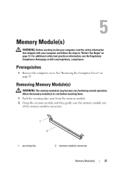
For additional safety best practices information, see the Regulatory Compliance Homepage at dell.com/regulatory_compliance. See "Removing the Computer Cover" on page 13. Removing Memory Module(s) WARNING: The memory module(s) may become very hot during normal operation. Prerequisites 1 Remove the computer cover. Allow the memory module(s) to cool before touching them. 1 Push the securing clips...
For additional safety best practices information, see the Regulatory Compliance Homepage at dell.com/regulatory_compliance. See "Removing the Computer Cover" on page 13. Removing Memory Module(s) WARNING: The memory module(s) may become very hot during normal operation. Prerequisites 1 Remove the computer cover. Allow the memory module(s) to cool before touching them. 1 Push the securing clips...
Owner's Manual (PDF)
Page 28
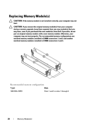
... installed in DIMM connectors 3 and 4. CAUTION: If you remove the original memory module(s) from Dell. Replacing Memory Module(s) CAUTION: If the memory module is not installed correctly, your computer during a memory upgrade, keep them separate from any new module(s) that you may have, even if you purchased the new module(s) from your computer may not...
... installed in DIMM connectors 3 and 4. CAUTION: If you remove the original memory module(s) from Dell. Replacing Memory Module(s) CAUTION: If the memory module is not installed correctly, your computer during a memory upgrade, keep them separate from any new module(s) that you may have, even if you purchased the new module(s) from your computer may not...
Owner's Manual (PDF)
Page 29
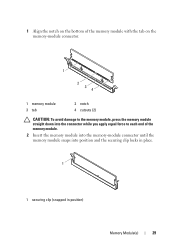
1 Align the notch on the bottom of the memory module with the tab on the memory-module connector. 1 2 3 4 1 memory module 3 tab 2 notch 4 cutouts (2) CAUTION: To avoid damage to the memory module, press the memory module straight down into the connector while you apply equal force to each end of the memory module. 2 Insert the memory module into the memory-module connector until the memory module snaps into position and the securing clip locks in place. 1 1 securing clip (snapped in position) Memory Module(s) 29
1 Align the notch on the bottom of the memory module with the tab on the memory-module connector. 1 2 3 4 1 memory module 3 tab 2 notch 4 cutouts (2) CAUTION: To avoid damage to the memory module, press the memory module straight down into the connector while you apply equal force to each end of the memory module. 2 Insert the memory module into the memory-module connector until the memory module snaps into position and the securing clip locks in place. 1 1 securing clip (snapped in position) Memory Module(s) 29
Owner's Manual (PDF)
Page 30
Postrequisites 1 Replace the computer cover. See "Replacing the Computer Cover" on page 25. 2 Follow the steps in "After Working Inside Your Computer" on page 15. 30 Memory Module(s)
Postrequisites 1 Replace the computer cover. See "Replacing the Computer Cover" on page 25. 2 Follow the steps in "After Working Inside Your Computer" on page 15. 30 Memory Module(s)
Owner's Manual (PDF)
Page 115
... the Mini-Card" on page 44. 5 Remove the graphics card. See "Removing the PCI-Express x1 Card(s)" on page 50. 3 Remove the memory module(s). See "Removing the Processor" on page 23. 2 Remove the Mini-Card, if applicable. Removing the System Board NOTE: Your computer's service ...the BIOS after you replace the system board. System-Board 115 For additional safety best practices information, see the Regulatory Compliance Homepage at dell.com/regulatory_compliance. 25 System Board WARNING: Before working inside your computer and follow the steps in "Before You Begin" on page 13...
... the Mini-Card" on page 44. 5 Remove the graphics card. See "Removing the PCI-Express x1 Card(s)" on page 50. 3 Remove the memory module(s). See "Removing the Processor" on page 23. 2 Remove the Mini-Card, if applicable. Removing the System Board NOTE: Your computer's service ...the BIOS after you replace the system board. System-Board 115 For additional safety best practices information, see the Regulatory Compliance Homepage at dell.com/regulatory_compliance. 25 System Board WARNING: Before working inside your computer and follow the steps in "Before You Begin" on page 13...
Owner's Manual (PDF)
Page 117
...(s). Express x1 Card(s)" on page 103. 2 Replace the processor fan and heat-sink assembly. See "Replacing Memory Module(s)" on page 51. 7 Replace the computer cover. See "Replacing the Mini-Card" on page 28. 6 Replace the Mini-Card, if applicable. Replacing the System ...
...(s). Express x1 Card(s)" on page 103. 2 Replace the processor fan and heat-sink assembly. See "Replacing Memory Module(s)" on page 51. 7 Replace the computer cover. See "Replacing the Mini-Card" on page 28. 6 Replace the Mini-Card, if applicable. Replacing the System ...
Owner's Manual (PDF)
Page 121
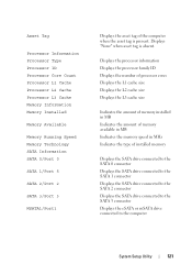
...Count Processor L1 Cache Processor L2 Cache Processor L3 Cache Memory Information Memory Installed Memory Available Memory Running Speed Memory Technology SATA Information SATA 0/Port 0 SATA 1/Port 5 SATA 2/Port 2 SATA 3/Port 3 MSATA1/Port1 Displays the asset tag of installed memory Displays the SATA drive connected to the SATA 0 ...cache size Displays the L2 cache size Displays the L3 cache size Indicates the amount of memory installed in MB Indicates the amount of memory available in MB Indicates the memory speed in MHz Indicates the type of the computer when the asset tag is absent. ...
...Count Processor L1 Cache Processor L2 Cache Processor L3 Cache Memory Information Memory Installed Memory Available Memory Running Speed Memory Technology SATA Information SATA 0/Port 0 SATA 1/Port 5 SATA 2/Port 2 SATA 3/Port 3 MSATA1/Port1 Displays the asset tag of installed memory Displays the SATA drive connected to the SATA 0 ...cache size Displays the L2 cache size Displays the L3 cache size Indicates the amount of memory installed in MB Indicates the amount of memory available in MB Indicates the memory speed in MHz Indicates the type of the computer when the asset tag is absent. ...
Owner's Manual (PDF)
Page 126
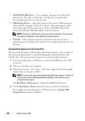
... Device Menu appears, listing all available boot devices. 4 On the Boot Device Menu choose the device you see the Microsoft Windows desktop. Insert the memory device into a USB connector and restart the computer. Changing Boot Sequence for the Current Boot You can use this feature to change the current boot... sequence, for example, to boot from the optical drive to run Dell Diagnostics from a USB device, connect the USB device to boot from the network. Then shut down your device is restored at the next boot. 1...
... Device Menu appears, listing all available boot devices. 4 On the Boot Device Menu choose the device you see the Microsoft Windows desktop. Insert the memory device into a USB connector and restart the computer. Changing Boot Sequence for the Current Boot You can use this feature to change the current boot... sequence, for example, to boot from the optical drive to run Dell Diagnostics from a USB device, connect the USB device to boot from the network. Then shut down your device is restored at the next boot. 1...


