Owner's Manual (PDF)
Page 4
5 Memory Module(s 27 Prerequisites 27 Removing Memory Module(s 27 Replacing Memory Module(s 28 Postrequisites 30 6 Front Bezel 31 Prerequisites 31 Removing the Front Bezel 31 Replacing the Front Bezel 33 Postrequisites 34 7 Graphics-Card Bracket (optional) . . . . . 35 Prerequisites 35 Removing the Graphics-Card Bracket 35 Replacing the Graphics-Card Bracket 36 Postrequisites 36 4 Contents
5 Memory Module(s 27 Prerequisites 27 Removing Memory Module(s 27 Replacing Memory Module(s 28 Postrequisites 30 6 Front Bezel 31 Prerequisites 31 Removing the Front Bezel 31 Replacing the Front Bezel 33 Postrequisites 34 7 Graphics-Card Bracket (optional) . . . . . 35 Prerequisites 35 Removing the Graphics-Card Bracket 35 Replacing the Graphics-Card Bracket 36 Postrequisites 36 4 Contents
Owner's Manual (PDF)
Page 8
16 Top Cover 77 Prerequisites 77 Removing the Top Cover 77 Replacing the Top Cover 78 Postrequisites 79 17 Top I/O Panel 81 Prerequisites 81 Removing the Top I/O Panel 81 Replacing the Top I/O Panel 83 Postrequisites 83 18 Front USB Panel 85 Prerequisites 85 Removing the Front USB Panel 85 Replacing the Front USB Panel 86 Postrequisites 87 8 Contents
16 Top Cover 77 Prerequisites 77 Removing the Top Cover 77 Replacing the Top Cover 78 Postrequisites 79 17 Top I/O Panel 81 Prerequisites 81 Removing the Top I/O Panel 81 Replacing the Top I/O Panel 83 Postrequisites 83 18 Front USB Panel 85 Prerequisites 85 Removing the Front USB Panel 85 Replacing the Front USB Panel 86 Postrequisites 87 8 Contents
Owner's Manual (PDF)
Page 9
19 Power Button Module 89 Prerequisites 89 Removing the Power Button Module 90 Replacing the Power Button Module 91 Postrequisites 91 20 Chassis Fan 93 Prerequisites 93 Removing the Chassis Fan 94 Replacing the Chassis Fan 95 Postrequisites 95 21 Processor Fan and Heat-Sink Assembly . 97 Prerequisites 97 Removing the Processor Fan and Heat-Sink Assembly. 97 Replacing the Processor Fan and Heat-Sink Assembly 99 Postrequisites 99 Contents 9
19 Power Button Module 89 Prerequisites 89 Removing the Power Button Module 90 Replacing the Power Button Module 91 Postrequisites 91 20 Chassis Fan 93 Prerequisites 93 Removing the Chassis Fan 94 Replacing the Chassis Fan 95 Postrequisites 95 21 Processor Fan and Heat-Sink Assembly . 97 Prerequisites 97 Removing the Processor Fan and Heat-Sink Assembly. 97 Replacing the Processor Fan and Heat-Sink Assembly 99 Postrequisites 99 Contents 9
Owner's Manual (PDF)
Page 13
... and Connected Devices CAUTION: To avoid losing data, save and close all open files and exit all open programs before you turn off . NOTE: If you are using a different operating system, see the Regulatory Compliance Homepage at dell.com/regulatory_compliance. Before you finish working inside the computer, replace all covers, panels, and screws before opening the computer cover or panels. After you Begin 13 Microsoft Windows...
... and Connected Devices CAUTION: To avoid losing data, save and close all open files and exit all open programs before you turn off . NOTE: If you are using a different operating system, see the Regulatory Compliance Homepage at dell.com/regulatory_compliance. Before you finish working inside the computer, replace all covers, panels, and screws before opening the computer cover or panels. After you Begin 13 Microsoft Windows...
Owner's Manual (PDF)
Page 14
...; Hex nut driver • Flash BIOS executable update program available at the back of the components inside your computer and then unplug the cable from the network device. Some cables have connectors with locking tabs or thumb-screws that the connectors and ports are correctly oriented and aligned. CAUTION: Only a certified service technician is authorized to remove the computer cover and access any connector...
...; Hex nut driver • Flash BIOS executable update program available at the back of the components inside your computer and then unplug the cable from the network device. Some cables have connectors with locking tabs or thumb-screws that the connectors and ports are correctly oriented and aligned. CAUTION: Only a certified service technician is authorized to remove the computer cover and access any connector...
Owner's Manual (PDF)
Page 15
... do so may damage your computer. • Turn on your computer • Connect your computer. 2 After Working Inside Your Computer After you complete replacement procedures, ensure the following: • Replace all screws and ensure no stray screws remain inside your computer • Connect any external devices, cables, cards, and any other part you removed before working on your computer and all screws and...
... do so may damage your computer. • Turn on your computer • Connect your computer. 2 After Working Inside Your Computer After you complete replacement procedures, ensure the following: • Replace all screws and ensure no stray screws remain inside your computer • Connect any external devices, cables, cards, and any other part you removed before working on your computer and all screws and...
Owner's Manual (PDF)
Page 20
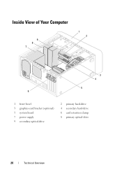
Inside View of Your Computer 9 8 7 1 2 3 4 5 6 1 front bezel 3 graphics-card bracket (optional) 5 system board 7 power supply 9 secondary optical-drive 2 primary hard-drive 4 secondary hard-drive 6 card retention clamp 8 primary optical-drive 20 Technical Overview
Inside View of Your Computer 9 8 7 1 2 3 4 5 6 1 front bezel 3 graphics-card bracket (optional) 5 system board 7 power supply 9 secondary optical-drive 2 primary hard-drive 4 secondary hard-drive 6 card retention clamp 8 primary optical-drive 20 Technical Overview
Owner's Manual (PDF)
Page 23
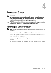
... the chassis, using a screw driver, if necessary. 3 Release the computer cover by sliding it away from the front of desk top space. Removing the Computer Cover NOTE: Ensure that you remove the security cable from the security cable slot (if applicable). 1 Lay the computer on page 13. Computer Cover 23 CAUTION: Ensure that secures the computer cover to support the computer with...
... the chassis, using a screw driver, if necessary. 3 Release the computer cover by sliding it away from the front of desk top space. Removing the Computer Cover NOTE: Ensure that you remove the security cable from the security cable slot (if applicable). 1 Lay the computer on page 13. Computer Cover 23 CAUTION: Ensure that secures the computer cover to support the computer with...
Owner's Manual (PDF)
Page 28
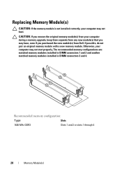
... memory configurations are: matched memory modules installed in DIMM connectors 1 and 2 and another matched memory modules installed in DIMM connectors 3 and 4. Otherwise, your computer may have, even if you purchased the new module(s) from Dell. Recommended memory configuration: Type Slots 1600 MHz DDR3 Slots 1 and 2 or slots 1 through 4 28 Memory Module(s) CAUTION: If you remove the original memory module(s) from your computer during a memory upgrade, keep them separate from any new module(s) that you may not boot...
... memory configurations are: matched memory modules installed in DIMM connectors 1 and 2 and another matched memory modules installed in DIMM connectors 3 and 4. Otherwise, your computer may have, even if you purchased the new module(s) from Dell. Recommended memory configuration: Type Slots 1600 MHz DDR3 Slots 1 and 2 or slots 1 through 4 28 Memory Module(s) CAUTION: If you remove the original memory module(s) from your computer during a memory upgrade, keep them separate from any new module(s) that you may not boot...
Owner's Manual (PDF)
Page 62
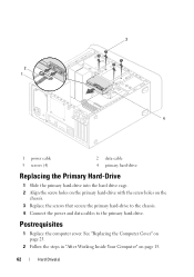
3 2 1 4 1 power cable 3 screws (4) 2 data cable 4 primary hard-drive Replacing the Primary Hard-Drive 1 Slide the primary hard-drive into the hard drive cage. 2 Align the screw holes on the primary hard-drive with the screw holes on page 15. 62 Hard Drive(s) See "Replacing the Computer Cover" on page 25. 2 Follow the steps in "After Working Inside Your Computer" on the chassis. 3 Replace the screws that secure the primary hard-drive to the chassis. 4 Connect the power and data cables to the primary hard-drive. Postrequisites 1 Replace the computer cover.
3 2 1 4 1 power cable 3 screws (4) 2 data cable 4 primary hard-drive Replacing the Primary Hard-Drive 1 Slide the primary hard-drive into the hard drive cage. 2 Align the screw holes on the primary hard-drive with the screw holes on page 15. 62 Hard Drive(s) See "Replacing the Computer Cover" on page 25. 2 Follow the steps in "After Working Inside Your Computer" on the chassis. 3 Replace the screws that secure the primary hard-drive to the chassis. 4 Connect the power and data cables to the primary hard-drive. Postrequisites 1 Replace the computer cover.
Owner's Manual (PDF)
Page 65
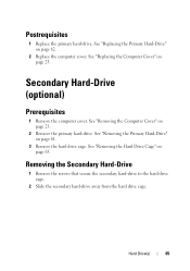
... 23. 2 Remove the primary hard-drive. Hard Drive(s) 65 See "Removing the Computer Cover" on page 25. Removing the Secondary Hard-Drive 1 Remove the screws that secure the secondary hard-drive to the hard drive cage. 2 Slide the secondary hard-drive away from the hard drive cage. See "Removing the Primary Hard-Drive" on page 63. See "Removing the Hard Drive Cage" on page 61. 3 Remove the hard drive cage. Secondary Hard-Drive (optional) Prerequisites 1 Remove the computer cover. See "Replacing the Primary Hard-Drive" on...
... 23. 2 Remove the primary hard-drive. Hard Drive(s) 65 See "Removing the Computer Cover" on page 25. Removing the Secondary Hard-Drive 1 Remove the screws that secure the secondary hard-drive to the hard drive cage. 2 Slide the secondary hard-drive away from the hard drive cage. See "Removing the Primary Hard-Drive" on page 63. See "Removing the Hard Drive Cage" on page 61. 3 Remove the hard drive cage. Secondary Hard-Drive (optional) Prerequisites 1 Remove the computer cover. See "Replacing the Primary Hard-Drive" on...

Owner's Manual (PDF)
Page 107
... and follow the steps in "Before You Begin" on page 21. 2 Press the battery-release lever to the manufacturer's instructions. Prerequisites 1 Remove the computer cover. See "System Setup" on page 119 for instructions on entering the system setup program. 1 Locate the battery socket on page 23. WARNING: A battery may explode if installed incorrectly. Removing the Coin-Cell Battery CAUTION: Removing the coin-cell battery resets the BIOS settings to default.
... and follow the steps in "Before You Begin" on page 21. 2 Press the battery-release lever to the manufacturer's instructions. Prerequisites 1 Remove the computer cover. See "System Setup" on page 119 for instructions on entering the system setup program. 1 Locate the battery socket on page 23. WARNING: A battery may explode if installed incorrectly. Removing the Coin-Cell Battery CAUTION: Removing the coin-cell battery resets the BIOS settings to default.
Owner's Manual (PDF)
Page 115
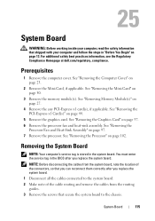
... applicable. NOTE: Before disconnecting the cables from the system board, note the location of the cable routing and remove the cables from the routing guides. 3 Remove the screws that secure the system board to the chassis. System-Board 115 You must enter the service tag in the BIOS after you replace the system board. 1 Disconnect all the cables connected to the system board. 2 Make note of the connectors, so...
... applicable. NOTE: Before disconnecting the cables from the system board, note the location of the cable routing and remove the cables from the routing guides. 3 Remove the screws that secure the system board to the chassis. System-Board 115 You must enter the service tag in the BIOS after you replace the system board. 1 Disconnect all the cables connected to the system board. 2 Make note of the connectors, so...
Owner's Manual (PDF)
Page 117
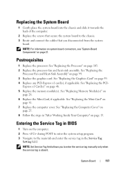
.... NOTE: Set Service Tag field allows you disconnected from the system board. NOTE: For information on system board connectors, see "System-Board Components" on page 103. 2 Replace the processor fan and heat-sink assembly. See "Replacing the Computer Cover" on page 25. 8 Follow the steps in "After Working Inside Your Computer" on page 28. 6 Replace the Mini-Card, if applicable. See "Replacing Memory Module(s)" on...
.... NOTE: Set Service Tag field allows you disconnected from the system board. NOTE: For information on system board connectors, see "System-Board Components" on page 103. 2 Replace the processor fan and heat-sink assembly. See "Replacing the Computer Cover" on page 25. 8 Follow the steps in "After Working Inside Your Computer" on page 28. 6 Replace the Mini-Card, if applicable. See "Replacing Memory Module(s)" on...
Owner's Manual (PDF)
Page 119
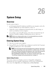
... about the hardware installed in your computer • set or change system setup, it , and then press . Entering System Setup 1 Turn on NOTE: Before you change a user-selectable option, such as the user password, type of the hard drive, and so on • change the system configuration information after you add, change, or remove any hardware in your computer, such as the amount of RAM, the size of hard drive installed, enabling or disabling base devices, and so...
... about the hardware installed in your computer • set or change system setup, it , and then press . Entering System Setup 1 Turn on NOTE: Before you change a user-selectable option, such as the user password, type of the hard drive, and so on • change the system configuration information after you add, change, or remove any hardware in your computer, such as the amount of RAM, the size of hard drive installed, enabling or disabling base devices, and so...

Owner's Manual (PDF)
Page 120
... make changes to your computer and make that define the configuration of the computer when the service tag is present Displays a field to the Setup Item. System Setup Options NOTE: Depending on the left side of the system setup window and contains information about that option and available settings. Key Functions - As an option is absent 120 System Setup Utility Setup Item - This field appears below the Help Screen and lists keys...
... make changes to your computer and make that define the configuration of the computer when the service tag is present Displays a field to the Setup Item. System Setup Options NOTE: Depending on the left side of the system setup window and contains information about that option and available settings. Key Functions - As an option is absent 120 System Setup Utility Setup Item - This field appears below the Help Screen and lists keys...

Owner's Manual (PDF)
Page 122
... Disabled (Enabled by default) • CPU XD Support - Enabled or Disabled (Enabled by default) • Onboard LAN Boot ROM - Enabled or Disabled (Enabled by default) • SATA Mode - Enabled or Disabled (Enabled by default) • Onboard Audio Controller - Enabled or Disabled (Disabled by default) • Intel Virtualization Technology - Enabled or Disabled (Enabled by default) 122 System Setup Utility AHCI; Enabled or Disabled (Enabled by default) • Rear USB Ports - Enabled or Disabled (Enabled by default) • Front USB Ports - Enabled or Disabled (Enabled...
... Disabled (Enabled by default) • CPU XD Support - Enabled or Disabled (Enabled by default) • Onboard LAN Boot ROM - Enabled or Disabled (Enabled by default) • SATA Mode - Enabled or Disabled (Enabled by default) • Onboard Audio Controller - Enabled or Disabled (Disabled by default) • Intel Virtualization Technology - Enabled or Disabled (Enabled by default) 122 System Setup Utility AHCI; Enabled or Disabled (Enabled by default) • Rear USB Ports - Enabled or Disabled (Enabled by default) • Front USB Ports - Enabled or Disabled (Enabled...
Owner's Manual (PDF)
Page 125
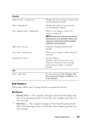
... an error message. System Setup Utility 125 The computer attempts to boot from the floppy disk drive. Enabled or Disabled (Disabled by default) Allows to set , change, or delete the supervisor password NOTE: Deleting the supervisor password will delete the user password. Boot Options • Diskette Drive - Security Supervisor Password User Password Set Supervisor Password HDD Protection Set User Password Password Check Exit Exit options Displays the status of supervisor password (Not Installed by default) Displays the status of user password (Not Installed by default) Allows to set...
... an error message. System Setup Utility 125 The computer attempts to boot from the floppy disk drive. Enabled or Disabled (Disabled by default) Allows to set , change, or delete the supervisor password NOTE: Deleting the supervisor password will delete the user password. Boot Options • Diskette Drive - Security Supervisor Password User Password Set Supervisor Password HDD Protection Set User Password Password Check Exit Exit options Displays the status of supervisor password (Not Installed by default) Displays the status of user password (Not Installed by default) Allows to set...
Owner's Manual (PDF)
Page 126
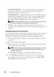
... device and adds the USB flash option to a USB device, the device must be bootable. If no operating system is restored at the next boot. 1 If you are booting from the Drivers and Utilities disc. • CD/DVD/CD-RW Drive - The computer attempts to a USB connector. 2 Turn on the network, the computer generates an error message. The Boot Device Menu appears, listing all available boot devices. 4 On the Boot Device Menu choose the device you see the Microsoft Windows desktop. Changing Boot...
... device and adds the USB flash option to a USB device, the device must be bootable. If no operating system is restored at the next boot. 1 If you are booting from the Drivers and Utilities disc. • CD/DVD/CD-RW Drive - The computer attempts to a USB connector. 2 Turn on the network, the computer generates an error message. The Boot Device Menu appears, listing all available boot devices. 4 On the Boot Device Menu choose the device you see the Microsoft Windows desktop. Changing Boot...

Owner's Manual (PDF)
Page 127
... CMOS setting. 1 Remove the computer cover. See "Removing the Computer Cover" on page 23. 2 Locate the 3-pin password reset jumper (PSWD) on page 13. See "System-Board Components" on page 21. 3 Remove the 2-pin jumper plug from the electrical outlet to restore it on page 119. 2 Use the arrow keys to highlight the Boot menu option and press to change the boot priority of the device. Changing Boot Sequence for Future Boots 1 Enter system setup...
... CMOS setting. 1 Remove the computer cover. See "Removing the Computer Cover" on page 23. 2 Locate the 3-pin password reset jumper (PSWD) on page 13. See "System-Board Components" on page 21. 3 Remove the 2-pin jumper plug from the electrical outlet to restore it on page 119. 2 Use the arrow keys to highlight the Boot menu option and press to change the boot priority of the device. Changing Boot Sequence for Future Boots 1 Enter system setup...


