Owner's Manual
Page 6
... Reader 121 Optical Drive 123 Removing an Optical Drive 123 Installing an Optical Drive 125 Processor Airflow Shroud 128 Removing the Processor Airflow Shroud Assembly 128 Installing the Processor Airflow Shroud Assembly 129 Processor 129 Removing the Processor 129 Installing the Processor 130 Fans 132 Removing the Card Fan 132 Installing the Card Fan 134 Removing...
... Reader 121 Optical Drive 123 Removing an Optical Drive 123 Installing an Optical Drive 125 Processor Airflow Shroud 128 Removing the Processor Airflow Shroud Assembly 128 Installing the Processor Airflow Shroud Assembly 129 Processor 129 Removing the Processor 129 Installing the Processor 130 Fans 132 Removing the Card Fan 132 Installing the Card Fan 134 Removing...
Owner's Manual
Page 11
... Support - processors, optical drives, and USB devices. Find It Here • Solutions - support.dell.com NOTE: Select your region or business segment to personalize my desktop Windows Help and Support 1 To access Windows Help and Support: • In Windows XP, click Start... Software. depending on the screen. Contact information, service call status, support history, service contract, and online discussions with other Dell customers • Upgrades - If you reinstall the To download Desktop System Software: operating system on my computer configuration, product specifications...
... Support - processors, optical drives, and USB devices. Find It Here • Solutions - support.dell.com NOTE: Select your region or business segment to personalize my desktop Windows Help and Support 1 To access Windows Help and Support: • In Windows XP, click Start... Software. depending on the screen. Contact information, service call status, support history, service contract, and online discussions with other Dell customers • Upgrades - If you reinstall the To download Desktop System Software: operating system on my computer configuration, product specifications...

Owner's Manual
Page 49
... applications used in gaming and design applications. Optimizing for Greater Performance 49 NOTICE: Dell Technical Support will significantly increase graphics performance on page 169. Dell does not provide technical support for any hardware or software issues arising from overclocking ...different subsystems within the system BIOS. Understanding CPU Overclocking NOTICE: Dell does not recommend operating the processor or other system components beyond the factory default settings. Each graphics card includes at the factory default...
... applications used in gaming and design applications. Optimizing for Greater Performance 49 NOTICE: Dell Technical Support will significantly increase graphics performance on page 169. Dell does not provide technical support for any hardware or software issues arising from overclocking ...different subsystems within the system BIOS. Understanding CPU Overclocking NOTICE: Dell does not recommend operating the processor or other system components beyond the factory default settings. Each graphics card includes at the factory default...
Owner's Manual
Page 61
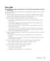
... same electrical outlet Printer Problems CAUTION: Before you begin any expansion cards, including graphics cards (see "System Board Components" on page 95). I F T H E P O W E R L I G H T I N T E R F E R E N C E - I F T H E P O W E R L I G H T I S B L I N K I S S T E A D Y A M B E R - Ensure that the processor power cable is in the Product Information Guide. I F T H E P O W E R L I G H T I N G A M B E R - A device may exist. • Ensure that the main power cable and front panel cable are : • Power...
... same electrical outlet Printer Problems CAUTION: Before you begin any expansion cards, including graphics cards (see "System Board Components" on page 95). I F T H E P O W E R L I G H T I N T E R F E R E N C E - I F T H E P O W E R L I G H T I S B L I N K I S S T E A D Y A M B E R - Ensure that the processor power cable is in the Product Information Guide. I F T H E P O W E R L I G H T I N G A M B E R - A device may exist. • Ensure that the main power cable and front panel cable are : • Power...
Owner's Manual
Page 65
... installed. - Ensure that the computer turns on properly. - Press a key on the keyboard, move the mouse, or press the power button to verify that the processor power cable is securely connected to the system board (see "System Board Components" on page 89). • If the power light is not receiving power...
... installed. - Ensure that the computer turns on properly. - Press a key on the keyboard, move the mouse, or press the power button to verify that the processor power cable is securely connected to the system board (see "System Board Components" on page 89). • If the power light is not receiving power...
Owner's Manual
Page 66
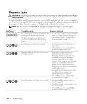
... working graphics card into a working electrical outlet (see "Power Problems" on page 61). • If the problem persists, contact Dell (see "Contacting Dell" on page 179). A possible graphics card failure has occurred. • Reseat any of the procedures in this section, follow the...modules (one module (see "Front View" on page 179). A possible processor failure has occurred. • Reseat the processor (see "Processor" on page 129). • If the problem persists, contact Dell (see "Contacting Dell" on page 92) and restart the computer. Diagnostic Lights CAUTION: Before...
... working graphics card into a working electrical outlet (see "Power Problems" on page 61). • If the problem persists, contact Dell (see "Contacting Dell" on page 179). A possible graphics card failure has occurred. • Reseat any of the procedures in this section, follow the...modules (one module (see "Front View" on page 179). A possible processor failure has occurred. • Reseat the processor (see "Processor" on page 129). • If the problem persists, contact Dell (see "Contacting Dell" on page 92) and restart the computer. Diagnostic Lights CAUTION: Before...
Owner's Manual
Page 90
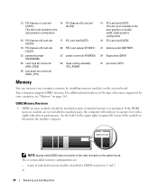
... PCI-Express x16 card slot (SLOT4) 19 PCI-Express x16 card slot (SLOT7) 22 password jumper (PASSWORD) 25 card cage fan connector (FAN_CAGE) 28 processor fan connector (FAN1_CPU) 17 PCI card slot (SLOT5) 20 RTC reset jumper (RTCRST) 23 power connector (POWER2) 26 liquid cooling assembly (TEC_PUMP) 15 ...in the dual-graphics or doublewidth, single graphics configuration. 18 PCI card slot (SLOT6) 21 battery socket (BATTERY) 24 floppy drive (DSKT) 27 processor (CPU) Memory You can increase your computer memory by your computer, see "Memory" on the upper-right or upper-left corner of the module ...
... PCI-Express x16 card slot (SLOT4) 19 PCI-Express x16 card slot (SLOT7) 22 password jumper (PASSWORD) 25 card cage fan connector (FAN_CAGE) 28 processor fan connector (FAN1_CPU) 17 PCI card slot (SLOT5) 20 RTC reset jumper (RTCRST) 23 power connector (POWER2) 26 liquid cooling assembly (TEC_PUMP) 15 ...in the dual-graphics or doublewidth, single graphics configuration. 18 PCI card slot (SLOT6) 21 battery socket (BATTERY) 24 floppy drive (DSKT) 27 processor (CPU) Memory You can increase your computer memory by your computer, see "Memory" on the upper-right or upper-left corner of the module ...
Owner's Manual
Page 91
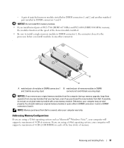
... memory module with a new memory module. NOTE: Memory purchased from Dell is covered under your original memory modules from the computer during a memory upgrade, keep them separate from Dell. Addressing Memory Configurations If you install modules in each of the four... slots) of memory. B A A matched pair of modules in DIMM connectors 1 B matched pair of the slowest module installed. • Be sure to install a single memory module in DIMM connector 1, the connector closest to the processor...
... memory module with a new memory module. NOTE: Memory purchased from Dell is covered under your original memory modules from the computer during a memory upgrade, keep them separate from Dell. Addressing Memory Configurations If you install modules in each of the four... slots) of memory. B A A matched pair of modules in DIMM connectors 1 B matched pair of the slowest module installed. • Be sure to install a single memory module in DIMM connector 1, the connector closest to the processor...

Owner's Manual
Page 92
... the Computer Cover" on page 86). 3 Press out the securing clip at each end of the memory module connector. 1 2 3 1 memory connector closest to 2 securing clips (2) processor 3 memory connector 4 Align the notch on the bottom of the procedures in this section, follow the safety instructions in the connector. 3 2 1 1 cutouts (2) 4 crossbar 2 memory module...
... the Computer Cover" on page 86). 3 Press out the securing clip at each end of the memory module connector. 1 2 3 1 memory connector closest to 2 securing clips (2) processor 3 memory connector 4 Align the notch on the bottom of the procedures in this section, follow the safety instructions in the connector. 3 2 1 1 cutouts (2) 4 crossbar 2 memory module...

Owner's Manual
Page 128
...computer cover (see "System Board Components" on page 89). 1 2 1 processor airflow shroud 2 captive screws (2) NOTICE: The processor heat sink is attached to the chassis, then rotate the shroud back. 5 Lift the processor airflow shroud out of the computer, and then set it . 3 Disconnect the... thermal interface. 4 Loosen the captive screws securing the processor airflow shroud to the processor airflow shroud. Processor Airflow Shroud CAUTION: Before you touch it aside. 128 Removing and Installing Parts CAUTION: The processor heat sink can get very hot during normal operation. ...
...computer cover (see "System Board Components" on page 89). 1 2 1 processor airflow shroud 2 captive screws (2) NOTICE: The processor heat sink is attached to the chassis, then rotate the shroud back. 5 Lift the processor airflow shroud out of the computer, and then set it . 3 Disconnect the... thermal interface. 4 Loosen the captive screws securing the processor airflow shroud to the processor airflow shroud. Processor Airflow Shroud CAUTION: Before you touch it aside. 128 Removing and Installing Parts CAUTION: The processor heat sink can get very hot during normal operation. ...

Owner's Manual
Page 129
...the POWER1 and POWER2 connectors (see "System Board Components" on page 89) on the system board. 4 Remove the airflow shroud (see "Removing the Processor Airflow Shroud Assembly" on page 128). 5 Push down and out on the socket release lever. NOTICE: To connect a network cable, first plug the... cable into the network port or device and then plug it into the computer. 7 Connect your system board. Installing the Processor Airflow Shroud Assembly 1 Follow the procedures in "Before You Begin" on page 85. 2 Remove the computer cover (see "Removing the Computer Cover" ...
...the POWER1 and POWER2 connectors (see "System Board Components" on page 89) on the system board. 4 Remove the airflow shroud (see "Removing the Processor Airflow Shroud Assembly" on page 128). 5 Push down and out on the socket release lever. NOTICE: To connect a network cable, first plug the... cable into the network port or device and then plug it into the computer. 7 Connect your system board. Installing the Processor Airflow Shroud Assembly 1 Follow the procedures in "Before You Begin" on page 85. 2 Remove the computer cover (see "Removing the Computer Cover" ...

Owner's Manual
Page 130
...unpainted metal surface on the socket is ready for the new processor. NOTICE: You must position the processor correctly in the release position so that the socket is not fully extended, move it to the processor and the computer when you turn on the computer. 2 ...If the release lever on the back of the computer. 1 Unpack the new processor. 6 Lift the socket release lever and open the processor cover. 1 2 3 4 1 processor cover 4 socket release lever 2 processor 3 socket 7 Remove the processor from the socket. Leave the release lever extended in the socket to avoid permanent damage...
...unpainted metal surface on the socket is ready for the new processor. NOTICE: You must position the processor correctly in the release position so that the socket is not fully extended, move it to the processor and the computer when you turn on the computer. 2 ...If the release lever on the back of the computer. 1 Unpack the new processor. 6 Lift the socket release lever and open the processor cover. 1 2 3 4 1 processor cover 4 socket release lever 2 processor 3 socket 7 Remove the processor from the socket. Leave the release lever extended in the socket to avoid permanent damage...

Owner's Manual
Page 131
... cable, first plug the cable into the network port or device and then plug it into place to secure the processor. 7 Replace the processor airflow shroud (see "Installing the Processor Airflow Shroud Assembly" on page 129). 8 Reconnect the power cables to the POWER1 and POWER2 connectors (see "System... or bend the pins on page 159). Removing and Installing Parts 131 3 Align the pin-1 corner of the processor and socket. 1 2 3 5 4 1 processor cover 4 socket release lever 2 processor 5 socket pin-1 indicator 3 socket NOTICE: Socket pins are delicate. To avoid damage, ensure that the...
... cable, first plug the cable into the network port or device and then plug it into place to secure the processor. 7 Replace the processor airflow shroud (see "Installing the Processor Airflow Shroud Assembly" on page 129). 8 Reconnect the power cables to the POWER1 and POWER2 connectors (see "System... or bend the pins on page 159). Removing and Installing Parts 131 3 Align the pin-1 corner of the processor and socket. 1 2 3 5 4 1 processor cover 4 socket release lever 2 processor 5 socket pin-1 indicator 3 socket NOTICE: Socket pins are delicate. To avoid damage, ensure that the...

Owner's Manual
Page 136
...the two bottom corners of the fan to detach the rubber grommets securing the fan to the processor airflow shroud, the lift the fan to detach the two remaining grommets. 3 2 1 1 rubber grommet (4) 2 CPU fan 3 processor airflow shroud Installing the CPU Fan 1 With the fan power cable oriented downward, align the rubber... grommets in the fan with the holes in each corner of the fan. 136 Removing and Installing Parts 4 Remove the processor airflow shroud (see "Removing the Processor Airflow Shroud Assembly" on page 128). 5 In succession, carefully pull on the side of the...
...the two bottom corners of the fan to detach the rubber grommets securing the fan to the processor airflow shroud, the lift the fan to detach the two remaining grommets. 3 2 1 1 rubber grommet (4) 2 CPU fan 3 processor airflow shroud Installing the CPU Fan 1 With the fan power cable oriented downward, align the rubber... grommets in the fan with the holes in each corner of the fan. 136 Removing and Installing Parts 4 Remove the processor airflow shroud (see "Removing the Processor Airflow Shroud Assembly" on page 128). 5 In succession, carefully pull on the side of the...

Owner's Manual
Page 137
... Components" on page 89). 4 Replace the computer cover (see "Replacing the Computer Cover" on page 159). 3 2 1 1 rubber grommet (4) 2 CPU fan 3 processor airflow shroud 2 Replace the processor airflow shroud (see "Installing the Processor Airflow Shroud Assembly" on page 129). 3 Connect the fan cable to electrical outlets, and then turn them on. Removing the Optional...
... Components" on page 89). 4 Replace the computer cover (see "Replacing the Computer Cover" on page 159). 3 2 1 1 rubber grommet (4) 2 CPU fan 3 processor airflow shroud 2 Replace the processor airflow shroud (see "Installing the Processor Airflow Shroud Assembly" on page 129). 3 Connect the fan cable to electrical outlets, and then turn them on. Removing the Optional...

Owner's Manual
Page 156
...page 85. 2 Remove the computer cover (see "Removing the Computer Cover" on page 86). 3 Remove any full-length expansion cards (see "Removing the Processor Airflow Shroud Assembly" on page 128). 5 Disconnect the front fan and the card fan from the I/O panel connector by pulling the cable loop. 2 1 ...1 Front I /O Panel CAUTION: Before you are sure to computer problems. 4 Remove the processor airflow shroud (see "Removing PCI and PCI Express Cards" on page 95). An incorrectly routed or a disconnected cable could lead to re-route cables ...
...page 85. 2 Remove the computer cover (see "Removing the Computer Cover" on page 86). 3 Remove any full-length expansion cards (see "Removing the Processor Airflow Shroud Assembly" on page 128). 5 Disconnect the front fan and the card fan from the I/O panel connector by pulling the cable loop. 2 1 ...1 Front I /O Panel CAUTION: Before you are sure to computer problems. 4 Remove the processor airflow shroud (see "Removing PCI and PCI Express Cards" on page 95). An incorrectly routed or a disconnected cable could lead to re-route cables ...

Owner's Manual
Page 157
...the screw holes on the chassis, and then tighten the four mounting screws. 4 Connect the control-panel cable to the system board. 7 Replace the processor airflow shroud (see "Replacing the Computer Cover" on the computer, replace the battery. Discard used batteries according to remove the I /O Panel CAUTION: Before... cards (see "Installing PCI and PCI Express Cards" on page 97) that you begin any of the I /O panel connector. 5 Replace the processor and card fan assembly. 6 Connect the front fan and the card fan to the I /O panel. 9 Replace the computer cover (see "Installing the...
...the screw holes on the chassis, and then tighten the four mounting screws. 4 Connect the control-panel cable to the system board. 7 Replace the processor airflow shroud (see "Replacing the Computer Cover" on the computer, replace the battery. Discard used batteries according to remove the I /O Panel CAUTION: Before... cards (see "Installing PCI and PCI Express Cards" on page 97) that you begin any of the I /O panel connector. 5 Replace the processor and card fan assembly. 6 Connect the front fan and the card fan to the I /O panel. 9 Replace the computer cover (see "Installing the...
Owner's Manual
Page 161
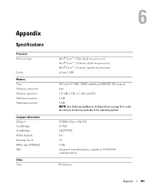
... Southbridge DMA channels Interrupt levels BIOS chip (NVRAM) NIC Video Type Intel® Core™ 2 Duo (dual-core processor) Intel® Core™ 2 Extreme (dual-core processor) Intel® Core™ 2 Extreme (quad-core processor) at least 1 MB 800, and 667-MHz DDR2 unbuffered SDRAM; SLI memory four 512 MB, 1 GB, or 2 GB...
... Southbridge DMA channels Interrupt levels BIOS chip (NVRAM) NIC Video Type Intel® Core™ 2 Duo (dual-core processor) Intel® Core™ 2 Extreme (dual-core processor) Intel® Core™ 2 Extreme (quad-core processor) at least 1 MB 800, and 667-MHz DDR2 unbuffered SDRAM; SLI memory four 512 MB, 1 GB, or 2 GB...
Owner's Manual
Page 167
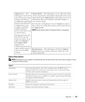
...about each option listed in the Options Field are changeable. NOTE: Not all settings listed in the Options List. System System Info Processor Info Memory Info PCI Info Date/Time Lists system information, such as listed. Indicates the expansion card type by DIMM slot location.... to highlight an option. Scroll up - Options Field - Appendix 167 Key Functions - Identifies the processor type, clock speed, bus speed, L2 cache, L3 cache, ID, and whether the processor is highlighted, the Options Field displays more information about your computer and make that option and the...
...about each option listed in the Options Field are changeable. NOTE: Not all settings listed in the Options List. System System Info Processor Info Memory Info PCI Info Date/Time Lists system information, such as listed. Indicates the expansion card type by DIMM slot location.... to highlight an option. Scroll up - Options Field - Appendix 167 Key Functions - Identifies the processor type, clock speed, bus speed, L2 cache, L3 cache, ID, and whether the processor is highlighted, the Options Field displays more information about your computer and make that option and the...
Owner's Manual
Page 169
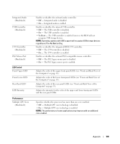
... CPU core technology is disabled. • On - NOTE: Operating systems with an additional core enabled. The PS/2 legacy mouse port is enabled. Specifies whether the processor has more than one core enabled. • Off - NOTE: The performance of the No Boot setting. Integrated Audio (On default) USB Controller (On default) 1394...
... CPU core technology is disabled. • On - NOTE: Operating systems with an additional core enabled. The PS/2 legacy mouse port is enabled. Specifies whether the processor has more than one core enabled. • Off - NOTE: The performance of the No Boot setting. Integrated Audio (On default) USB Controller (On default) 1394...


