Owner's Manual
Page 4
... a New Computer 43 Power Management Options in Windows XP 44 Standby Mode 44 Hibernate Mode 45 Power Options ... Settings 47 2 Optimizing for Greater Performance 49 Understanding Dual-Graphics Technology 49 Understanding CPU Overclocking 49 3 Dell™ QuickSet 51 4 Troubleshooting 53 Solving Problems 53 Battery Problems 53 Drive Problems 53 E-Mail, Modem...55 Error Messages 56 IEEE 1394 Device Problems 57 Keyboard Problems 57 Lockups and Software Problems 58 Memory Problems 59 Mouse Problems 60 Network Problems 60 Power Problems 61 Printer Problems 61 Scanner Problems 62...
... a New Computer 43 Power Management Options in Windows XP 44 Standby Mode 44 Hibernate Mode 45 Power Options ... Settings 47 2 Optimizing for Greater Performance 49 Understanding Dual-Graphics Technology 49 Understanding CPU Overclocking 49 3 Dell™ QuickSet 51 4 Troubleshooting 53 Solving Problems 53 Battery Problems 53 Drive Problems 53 E-Mail, Modem...55 Error Messages 56 IEEE 1394 Device Problems 57 Keyboard Problems 57 Lockups and Software Problems 58 Memory Problems 59 Mouse Problems 60 Network Problems 60 Power Problems 61 Printer Problems 61 Scanner Problems 62...

Owner's Manual
Page 5
... Drivers and Utilities Media 76 Restoring Your Operating System 78 Using Microsoft Windows System Restore 78 Using Dell PC Restore and Dell Factory Image Restore 79 Using the Operating System Media 82 Troubleshooting Software and Hardware Problems 83 5 ...Removing and Installing Parts 85 Before You Begin 85 Recommended Tools 85 Preparing to Work Inside Your Computer 85 Removing the Computer Cover 86 Inside View of Your Computer 88 System Board Components 89 Memory...
... Drivers and Utilities Media 76 Restoring Your Operating System 78 Using Microsoft Windows System Restore 78 Using Dell PC Restore and Dell Factory Image Restore 79 Using the Operating System Media 82 Troubleshooting Software and Hardware Problems 83 5 ...Removing and Installing Parts 85 Before You Begin 85 Recommended Tools 85 Preparing to Work Inside Your Computer 85 Removing the Computer Cover 86 Inside View of Your Computer 88 System Board Components 89 Memory...
Owner's Manual
Page 11
... personalize my desktop Windows Help and Support 1 To access Windows Help and Support: • In Windows XP, click Start and click Help and Support. • In Windows Vista™, click the Windows Vista .... Finding Information 11 Contact information, service call status, support history, service contract, and online discussions with other Dell customers • Upgrades - Service call and order status, and warranty and repair information • Service and ...updates appropriate for components, such as the memory, hard drive, and operating system • Customer Care -
... personalize my desktop Windows Help and Support 1 To access Windows Help and Support: • In Windows XP, click Start and click Help and Support. • In Windows Vista™, click the Windows Vista .... Finding Information 11 Contact information, service call status, support history, service contract, and online discussions with other Dell customers • Upgrades - Service call and order status, and warranty and repair information • Service and ...updates appropriate for components, such as the memory, hard drive, and operating system • Customer Care -

Owner's Manual
Page 15
...devices that you connect occasionally, such as digital video cameras and external storage devices. Setting Up and Using Your Computer 15 Dell recommends that typically remain connected, such as printers and keyboards. 7 IEEE 1394 connector Use the IEEE 1394 connector for ...high-speed data devices such as flash memory keys, cameras, or bootable USB devices. Front I/O Connectors 1 2 3 4 5 6 7 1 microphone connector Use the microphone connector to attach ...
...devices that you connect occasionally, such as digital video cameras and external storage devices. Setting Up and Using Your Computer 15 Dell recommends that typically remain connected, such as printers and keyboards. 7 IEEE 1394 connector Use the IEEE 1394 connector for ...high-speed data devices such as flash memory keys, cameras, or bootable USB devices. Front I/O Connectors 1 2 3 4 5 6 7 1 microphone connector Use the microphone connector to attach ...

Owner's Manual
Page 18
...Use the (green) line-out connector to attach a record/playback device such as flash memory keys, cameras, or bootable USB devices. Use the RCA S/PDIF connector to provide extremely...low bass extension. Use the (orange) subwoofer connector to attach multichannel-capable speakers. Use the (black) surround sound connector to attach a single subwoofer. 6 side surround sound connector 7 center subwoofer/LFE...that you connect occasionally, such as a cassette player, CD player, or VCR. NOTE: Dell recommends that you use the connector on the card. Use the (pink) microphone connector ...
...Use the (green) line-out connector to attach a record/playback device such as flash memory keys, cameras, or bootable USB devices. Use the RCA S/PDIF connector to provide extremely...low bass extension. Use the (orange) subwoofer connector to attach multichannel-capable speakers. Use the (black) surround sound connector to attach a single subwoofer. 6 side surround sound connector 7 center subwoofer/LFE...that you connect occasionally, such as a cassette player, CD player, or VCR. NOTE: Dell recommends that you use the connector on the card. Use the (pink) microphone connector ...
Owner's Manual
Page 41
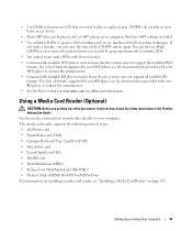
... For a list of formats supported by your BD player, see the documentation provided with CD recording techniques. The media card reader supports the following memory types: • xD-Picture card • SmartMedia card (SMC) • CompactFlash card Type I and II (CF I/II) • ...MicroDrive card • SecureDigital card (SD) • MiniSD card • MultiMediaCard (MMC) • Reduced-size MultiMediaCard (RS-MMC) • Memory Stick (MS/MS Pro/MS Duo/MS Pro Duo) For information on installing a media card reader, see the documentation provided with Roxio Creator. •...
... For a list of formats supported by your BD player, see the documentation provided with CD recording techniques. The media card reader supports the following memory types: • xD-Picture card • SmartMedia card (SMC) • CompactFlash card Type I and II (CF I/II) • ...MicroDrive card • SecureDigital card (SD) • MiniSD card • MultiMediaCard (MMC) • Reduced-size MultiMediaCard (RS-MMC) • Memory Stick (MS/MS Pro/MS Duo/MS Pro Duo) For information on installing a media card reader, see the documentation provided with Roxio Creator. •...
Owner's Manual
Page 42
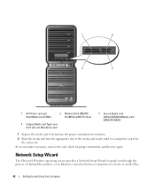
... reader until it is completely seated in a home or small office. 42 Setting Up and Using Your Computer 1 2 4 3 1 xD-Picture card and SmartMedia Card (SMC) 2 Memory Stick (MS/MS Pro/MS Duo/MS Pro Duo) 4 CompactFlash card Type I and II (CF I/II) and MicroDrive card 3 Secure Digital card (SD/miniSD)/MultiMedia...
... reader until it is completely seated in a home or small office. 42 Setting Up and Using Your Computer 1 2 4 3 1 xD-Picture card and SmartMedia Card (SMC) 2 Memory Stick (MS/MS Pro/MS Duo/MS Pro Duo) 4 CompactFlash card Type I and II (CF I/II) and MicroDrive card 3 Secure Digital card (SD/miniSD)/MultiMedia...
Owner's Manual
Page 45
.... When the computer exits from hibernate mode, the desktop is called a scheme. If the computer's hard drive becomes corrupted, Windows XP recreates the hibernate file automatically. Setting Up and Using Your Computer 45 Power Schemes Tab Each standard power setting is restored to the ... tab. Because hibernate mode requires a special file on your hard drive with enough disk space to store the contents of the computer memory, Dell creates an appropriately sized hibernate mode file before shipping the computer to entering hibernate mode. To access the Power Options Properties window: 1...
.... When the computer exits from hibernate mode, the desktop is called a scheme. If the computer's hard drive becomes corrupted, Windows XP recreates the hibernate file automatically. Setting Up and Using Your Computer 45 Power Schemes Tab Each standard power setting is restored to the ... tab. Because hibernate mode requires a special file on your hard drive with enough disk space to store the contents of the computer memory, Dell creates an appropriately sized hibernate mode file before shipping the computer to entering hibernate mode. To access the Power Options Properties window: 1...
Owner's Manual
Page 59
... hardware requirements needed to run the software. If necessary, install additional memory (see "Installing Memory" on page 92). • Reseat the memory modules (see "Memory" on page 90) to get a response by your computer, see "Memory" on page 161. • Run the Dell Diagnostics (see "Dell Diagnostics" on your computer. • Ensure that resolves the problem. •...
... hardware requirements needed to run the software. If necessary, install additional memory (see "Installing Memory" on page 92). • Reseat the memory modules (see "Memory" on page 90) to get a response by your computer, see "Memory" on page 161. • Run the Dell Diagnostics (see "Dell Diagnostics" on your computer. • Ensure that resolves the problem. •...
Owner's Manual
Page 61
... possible causes of interference are securely connected to resume normal operation. NOTE: If you begin any expansion cards, including graphics cards (see "Memory" on page 90). • Remove and then reinstall any of the procedures in this section, follow the safety instructions in the Product... E R F E R E N C E - See "Diagnostic Lights" on page 95). The computer is working by testing it with another device, such as a lamp. • Ensure that all memory modules (see "Removing PCI and PCI Express Cards" on page 66. E L I M I N A T E I S S T E A D Y A M B E R - Ensure that ...
... possible causes of interference are securely connected to resume normal operation. NOTE: If you begin any expansion cards, including graphics cards (see "Memory" on page 90). • Remove and then reinstall any of the procedures in this section, follow the safety instructions in the Product... E R F E R E N C E - See "Diagnostic Lights" on page 95). The computer is working by testing it with another device, such as a lamp. • Ensure that all memory modules (see "Removing PCI and PCI Express Cards" on page 66. E L I M I N A T E I S S T E A D Y A M B E R - Ensure that ...
Owner's Manual
Page 65
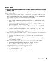
... illuminates and blinks or remains solid to indicate different states: • If the power light is green and the computer is not responding, see "Memory" on a power strip - Power Lights CAUTION: Before you begin any cards (see "Cards" on page 94). • Eliminate interference. Bypass power...system board (see "System Board Components" on page 89). • If the power light is turned on. - Remove and then reinstall the memory modules (see "Diagnostic Lights" on properly. - Reseat the power cable into an electrical outlet and that the processor power cable is securely connected...
... illuminates and blinks or remains solid to indicate different states: • If the power light is green and the computer is not responding, see "Memory" on a power strip - Power Lights CAUTION: Before you begin any cards (see "Cards" on page 94). • Eliminate interference. Bypass power...system board (see "System Board Components" on page 89). • If the power light is turned on. - Remove and then reinstall the memory modules (see "Diagnostic Lights" on properly. - Reseat the power cable into an electrical outlet and that the processor power cable is securely connected...
Owner's Manual
Page 66
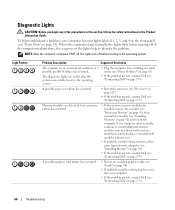
... occurred. • Reseat any of the lights help troubleshoot a problem, your computer (see "Installing Memory" on page 92). • If the problem persists, contact Dell (see "Contacting Dell" on page 13). If the computer malfunctions, the sequence of the procedures in this section, follow ...(see "Processor" on page 129). • If the problem persists, contact Dell (see "Contacting Dell" on page 179). Memory modules are detected, but a memory failure has occurred. • If two or more memory modules are not lit after the system successfully boots to identify the problem. If...
... occurred. • Reseat any of the lights help troubleshoot a problem, your computer (see "Installing Memory" on page 92). • If the problem persists, contact Dell (see "Contacting Dell" on page 13). If the computer malfunctions, the sequence of the procedures in this section, follow ...(see "Processor" on page 129). • If the problem persists, contact Dell (see "Contacting Dell" on page 179). Memory modules are detected, but a memory failure has occurred. • If two or more memory modules are not lit after the system successfully boots to identify the problem. If...
Owner's Manual
Page 67
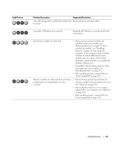
... • If available, install working memory of the same type into your computer (see "Memory" on page 161). • If the problem persists, contact Dell (see "Contacting Dell" on page 92) and restart the computer. Troubleshooting 67 No memory modules are using is supported by your... computer (see "Installing Memory" on page 92). • If the problem persists, contact Dell (see "Contacting Dell" on page 179). •...
... • If available, install working memory of the same type into your computer (see "Memory" on page 161). • If the problem persists, contact Dell (see "Contacting Dell" on page 92) and restart the computer. Troubleshooting 67 No memory modules are using is supported by your... computer (see "Installing Memory" on page 92). • If the problem persists, contact Dell (see "Contacting Dell" on page 179). •...

Owner's Manual
Page 69
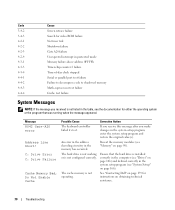
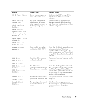
... failure Screen initialization failure Troubleshooting 69 Code 1-1-2 1-1-3 1-1-4 1-2-1 1-2-2 1-2-3 1-3 1-3-1 through 2-4-4 4-3-1 Cause Memory not being properly identified or used Memory failure above address 0FFFFh If you that the computer encountered a memory problem. Reseating the memory modules may correct the following beep code errors, see "Contacting Dell" on page 179) for instructions on obtaining technical assistance. If the problem...
... failure Screen initialization failure Troubleshooting 69 Code 1-1-2 1-1-3 1-1-4 1-2-1 1-2-2 1-2-3 1-3 1-3-1 through 2-4-4 4-3-1 Cause Memory not being properly identified or used Memory failure above address 0FFFFh If you that the computer encountered a memory problem. Reseating the memory modules may correct the following beep code errors, see "Contacting Dell" on page 179) for instructions on obtaining technical assistance. If the problem...
Owner's Manual
Page 70
...on page 166). See "Contacting Dell" on page 179 for either the operating system or the program that the hard drive is not listed in the table, see "System Setup" on page 106) and defined correctly in the memory has occurred. An error in ... 4-3-1 4-3-3 4-3-4 4-4-1 4-4-2 4-4-3 4-4-4 Cause Screen retrace failure Search for video ROM failure No timer tick Shutdown failure Gate A20 failure Unexpected interrupt in protected mode Memory failure above address 0FFFFh Timer-chip counter 2 failure Time-of-day clock stopped Serial or parallel port test failure Failure to decompress code to shadowed...
...on page 166). See "Contacting Dell" on page 179 for either the operating system or the program that the hard drive is not listed in the table, see "System Setup" on page 106) and defined correctly in the memory has occurred. An error in ... 4-3-1 4-3-3 4-3-4 4-4-1 4-4-2 4-4-3 4-4-4 Cause Screen retrace failure Search for video ROM failure No timer tick Shutdown failure Gate A20 failure Unexpected interrupt in protected mode Memory failure above address 0FFFFh Timer-chip counter 2 failure Time-of-day clock stopped Serial or parallel port test failure Failure to decompress code to shadowed...
Owner's Manual
Page 71
... An interrupt channel on page 166). The keyboard or system board may need to be located on page 166). Troubleshooting 71 Corrective Action See "Contacting Dell" on page 179 for instructions on the system board. The keyboard or system board may be replaced. Ensure that drive A or drive C is... at both ends. Message CH-2 Timer Error CMOS Battery State Low CMOS Checksum Failure CMOS System Options Not Set CMOS Display Type Mismatch CMOS Memory Size Mismatch CMOS Time and Date Not Set Diskette Boot Failure DMA Error DMA 1 Error DMA 2 Error FDD Controller Failure HDD Controller Failure...
... An interrupt channel on page 166). The keyboard or system board may need to be located on page 166). Troubleshooting 71 Corrective Action See "Contacting Dell" on page 179 for instructions on the system board. The keyboard or system board may be replaced. Ensure that drive A or drive C is... at both ends. Message CH-2 Timer Error CMOS Battery State Low CMOS Checksum Failure CMOS System Options Not Set CMOS Display Type Mismatch CMOS Memory Size Mismatch CMOS Time and Date Not Set Diskette Boot Failure DMA Error DMA 1 Error DMA 2 Error FDD Controller Failure HDD Controller Failure...

Owner's Manual
Page 74
...and allows you to select a test based on page 179). The following tests can be run . If you cannot resolve the problem, contact Dell (see "Contacting Dell" on the symptom of the problem you are having. NOTE: The Service Tag for the selected device. Displays error conditions encountered, error codes,...devices. NOTE: The device list may not display the names of all the components installed on your computer or all devices from system setup, memory, and various internal tests, and it appears and follow the instructions on your computer is located at the top of each test screen. For...
...and allows you to select a test based on page 179). The following tests can be run . If you cannot resolve the problem, contact Dell (see "Contacting Dell" on the symptom of the problem you are having. NOTE: The Service Tag for the selected device. Displays error conditions encountered, error codes,...devices. NOTE: The device list may not display the names of all the components installed on your computer or all devices from system setup, memory, and various internal tests, and it appears and follow the instructions on your computer is located at the top of each test screen. For...
Owner's Manual
Page 89
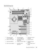
System Board Components 1 2 3 4 28 27 5 6 7 8 9 10 11 12 13 26 14 15 25 16 24 23 22 1 white memory module connectors (DIMM_1-2) 4 IDE drive connector (IDE) 7 power button (PWR_BT) 10 SATA connectors (SATA0-5) 17 21 20 18 19 2 black memory module connectors (DIMM_3-4) 3 hard drive fan connector (FAN_HDD) 5 front I/O panel connector (FRONTPANEL) 6 back LED connector 8 FlexBay connector (INT_USB) 9 main power connector (POWER1) 11 front USB connector (FRNT_USB) 12 front panel 1394 connector (FP1394) Removing and Installing Parts 89
System Board Components 1 2 3 4 28 27 5 6 7 8 9 10 11 12 13 26 14 15 25 16 24 23 22 1 white memory module connectors (DIMM_1-2) 4 IDE drive connector (IDE) 7 power button (PWR_BT) 10 SATA connectors (SATA0-5) 17 21 20 18 19 2 black memory module connectors (DIMM_3-4) 3 hard drive fan connector (FAN_HDD) 5 front I/O panel connector (FRONTPANEL) 6 back LED connector 8 FlexBay connector (INT_USB) 9 main power connector (POWER1) 11 front USB connector (FRNT_USB) 12 front panel 1394 connector (FP1394) Removing and Installing Parts 89
Owner's Manual
Page 90
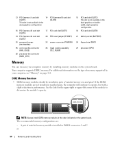
For additional information on the type of memory supported by your computer memory by installing memory modules on the upper-right or upper-left corner of matched memory size and speed. If the DDR2 memory modules are : - The recommended memory configurations are not installed in matched pairs, ...the computer will continue to determine the module's capacity. NOTE: Always install DDR2 memory modules in the order indicated on page 161. Your computer supports DDR2 memory. A pair of matched memory modules installed in pairs of the module to operate, but with a slight reduction...
For additional information on the type of memory supported by your computer memory by installing memory modules on the upper-right or upper-left corner of matched memory size and speed. If the DDR2 memory modules are : - The recommended memory configurations are not installed in matched pairs, ...the computer will continue to determine the module's capacity. NOTE: Always install DDR2 memory modules in the order indicated on page 161. Your computer supports DDR2 memory. A pair of matched memory modules installed in pairs of the module to operate, but with a slight reduction...
Owner's Manual
Page 91
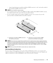
... 2 (white securing clips) connectors 3 and 4 (black securing clips) NOTICE: If you remove your original memory modules from the computer during a memory upgrade, keep them separate from Dell is covered under your computer will support a maximum of memory. If possible, do not pair an original memory module with a new memory module. Addressing Memory Configurations If you may not start...
... 2 (white securing clips) connectors 3 and 4 (black securing clips) NOTICE: If you remove your original memory modules from the computer during a memory upgrade, keep them separate from Dell is covered under your computer will support a maximum of memory. If possible, do not pair an original memory module with a new memory module. Addressing Memory Configurations If you may not start...


