Service Manual
Page 7
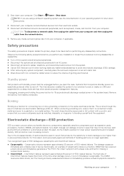
... represent approximately 80 percent of device functionality. Disconnect all attached network devices and peripherals, such as expansion cards, processors, memory DIMMs, and system boards. The internal power enables the system to Working on an anti-static mat. ● Wear shoes with a beep code emitted for lower power requirements and increased density, ESD protection is done through the use of handling parts are catastrophic and intermittent...
... represent approximately 80 percent of device functionality. Disconnect all attached network devices and peripherals, such as expansion cards, processors, memory DIMMs, and system boards. The internal power enables the system to Working on an anti-static mat. ● Wear shoes with a beep code emitted for lower power requirements and increased density, ESD protection is done through the use of handling parts are catastrophic and intermittent...

Service Manual
Page 28
... that covers the solid-state drive slot. 2. Follow the procedure in After working inside your computer. Steps 1. About this task The following image indicates the location of the coin-cell battery and provides a visual representation of the installation procedure. Remove the base cover. CAUTION: Removing the coin-cenn battery resets the BIOS setup program's settings to the system board. 4. About this task The following image indicates the location of...
... that covers the solid-state drive slot. 2. Follow the procedure in After working inside your computer. Steps 1. About this task The following image indicates the location of the coin-cell battery and provides a visual representation of the installation procedure. Remove the base cover. CAUTION: Removing the coin-cenn battery resets the BIOS setup program's settings to the system board. 4. About this task The following image indicates the location of...

Service Manual
Page 51
... Before working inside your computer. Remove the base cover. 3. Remove the system board. Remove the touchpad. Push the display hinge down and replace the single (M2x3) screw to secure the left display hinge to the system board. 7. About this location when installing system board for Inspiron 7300. 2. Disassembly and reassembly 51 Connect the coin-cell battery cable, fingerprint-reader cable, I/O-board cable, touchpad cable, keyboard cable and keyboardbacklit cable, speaker cable from the wireless-card. 6. Install the heat sink. 4. Install the 4-cell battery...
... Before working inside your computer. Remove the base cover. 3. Remove the system board. Remove the touchpad. Push the display hinge down and replace the single (M2x3) screw to secure the left display hinge to the system board. 7. About this location when installing system board for Inspiron 7300. 2. Disassembly and reassembly 51 Connect the coin-cell battery cable, fingerprint-reader cable, I/O-board cable, touchpad cable, keyboard cable and keyboardbacklit cable, speaker cable from the wireless-card. 6. Install the heat sink. 4. Install the 4-cell battery...
Service Manual
Page 57
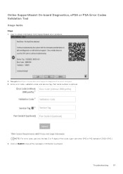
NOTE: For error code, use only the last 3 or 4 digits of the code. (user can enter 0142 or 142 instead of 2000-0142.) 4. Troubleshooting 57 Enter error code, validation code, and service tag. Click on Submit once all the necessary information is optional. Navigate to obtain information from SupportAssist error windows. 2. User to https://www.dell.com/support/diagnose/Pre-boot-Analysis. 3. Part serial number is entered. Online SupportAssist On-board Diagnostics, ePSA or PSA Error Codes Validation Tool Usage Guide Steps 1.
NOTE: For error code, use only the last 3 or 4 digits of the code. (user can enter 0142 or 142 instead of 2000-0142.) 4. Troubleshooting 57 Enter error code, validation code, and service tag. Click on Submit once all the necessary information is optional. Navigate to obtain information from SupportAssist error windows. 2. User to https://www.dell.com/support/diagnose/Pre-boot-Analysis. 3. Part serial number is entered. Online SupportAssist On-board Diagnostics, ePSA or PSA Error Codes Validation Tool Usage Guide Steps 1.
Service Manual
Page 61
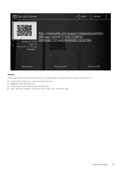
Results The link generated will take the customer to the Dell Support website which contains information on: ● Confirmation of the error code and result outcome ● Suggested Part Replacement ● If customer is still covered under Dell Warranty ● Case reference number if there is an open case under the service tag Troubleshooting 61
Results The link generated will take the customer to the Dell Support website which contains information on: ● Confirmation of the error code and result outcome ● Suggested Part Replacement ● If customer is still covered under Dell Warranty ● Case reference number if there is an open case under the service tag Troubleshooting 61

Service Manual
Page 63
.... Replace system board Coin-cell battery failure PCI, video card/chip failure Recovery image not found Recovery image found but invalid Power-rail failure System BIOS Flash incomplete Management Engine (ME) error Camera status light: Indicates whether the camera is unable to access the internet due to conduct a WiFi power cycle: NOTE: Some ISPs (Internet Service Providers) provide a modem/router combo device. Troubleshooting 63 LED codes (continued) Diagnostic light codes 2,3 2,4 2,5 2,6 2,7 2,8 3,1 3,2 3,3 3,4 3,5 3,6 3,7 Problem description No memory or RAM (Random-Access Memory...
.... Replace system board Coin-cell battery failure PCI, video card/chip failure Recovery image not found Recovery image found but invalid Power-rail failure System BIOS Flash incomplete Management Engine (ME) error Camera status light: Indicates whether the camera is unable to access the internet due to conduct a WiFi power cycle: NOTE: Some ISPs (Internet Service Providers) provide a modem/router combo device. Troubleshooting 63 LED codes (continued) Diagnostic light codes 2,3 2,4 2,5 2,6 2,7 2,8 3,1 3,2 3,3 3,4 3,5 3,6 3,7 Problem description No memory or RAM (Random-Access Memory...
Setup and Specifications
Page 3
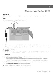
... the computer. 2. Finish operating system setup. For Ubuntu: Follow the on -screen instructions to a secured wireless network, enter the password for Windows updates. Actual product may differ in this task NOTE: The images in color. For Windows: Follow the on -screen instructions to the internet, sign-in with or create a Microsoft account. When setting up, Dell recommends that you ordered. For more information about installing and configuring Ubuntu, see the...
... the computer. 2. Finish operating system setup. For Ubuntu: Follow the on -screen instructions to a secured wireless network, enter the password for Windows updates. Actual product may differ in this task NOTE: The images in color. For Windows: Follow the on -screen instructions to the internet, sign-in with or create a Microsoft account. When setting up, Dell recommends that you ordered. For more information about installing and configuring Ubuntu, see the...

Setup and Specifications
Page 9
... your Vostro 5301. Processors NOTE: Global Standard Products (GSP) are the new security features that only privileged system software can access them. They ensure the same platform is available for availability and synchronized transitions on the configuration ordered and manufacturing variability. When you configure together, it can lead to implement global IT standards by protecting NT LAN Manager (NTLM) password hashes...
... your Vostro 5301. Processors NOTE: Global Standard Products (GSP) are the new security features that only privileged system software can access them. They ensure the same platform is available for availability and synchronized transitions on the configuration ordered and manufacturing variability. When you configure together, it can lead to implement global IT standards by protecting NT LAN Manager (NTLM) password hashes...
Setup and Specifications
Page 19
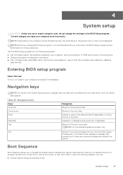
... about the hardware installed in this task Turn on (or restart) your computer work incorrectly. During the Power-on the computer and its installed devices, the items listed in your computer, such as the amount of RAM and the size of the hard drive. ● Change the system configuration information. ● Set or change a user-selectable option, such as the user password, type of the System Setup options, changes that you make your computer...
... about the hardware installed in this task Turn on (or restart) your computer work incorrectly. During the Power-on the computer and its installed devices, the items listed in your computer, such as the amount of RAM and the size of the hard drive. ● Change the system configuration information. ● Set or change a user-selectable option, such as the user password, type of the System Setup options, changes that you make your computer...

Setup and Specifications
Page 20
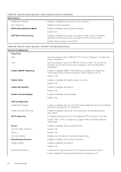
... Service Code Ownership Tag Signed Firmware Update Battery Primary Displays the BIOS version number. Displays the ownership tag of the computer. NOTE: It is enabled. Displays the ownership date of the computer. Displays the express service code of the computer. Displays whether the signed firmware update is recommended to access the System Setup screen. The boot menu options are : ● Removable Drive (if available) ● STXXXX Drive (if available) NOTE: XXX denotes the SATA drive number. ● Optical Drive...
... Service Code Ownership Tag Signed Firmware Update Battery Primary Displays the BIOS version number. Displays the ownership tag of the computer. NOTE: It is enabled. Displays the ownership date of the computer. Displays the express service code of the computer. Displays whether the signed firmware update is recommended to access the System Setup screen. The boot menu options are : ● Removable Drive (if available) ● STXXXX Drive (if available) NOTE: XXX denotes the SATA drive number. ● Optical Drive...
Setup and Specifications
Page 22
... USB ports to the time take effect immediately. Default: RAID. Enables or disables the camera. The keyboard illumination will always be functional in an operating system environment. Changes to be off. 22 System setup Enable Microphone Enables or disables microphone. Default: ON. Keyboard Illumination Configures the operating mode of the integrated SATA hard drive controller. Default: Disabled. Displays the boot sequence. Sets the computer time in MM/DD/YYYY format. Default: ON. Drives M.2 PCIe SSD-0/SATA-2 SATA-0 Drive Information Miscellaneous Devices...
... USB ports to the time take effect immediately. Default: RAID. Enables or disables the camera. The keyboard illumination will always be functional in an operating system environment. Changes to be off. 22 System setup Enable Microphone Enables or disables microphone. Default: ON. Keyboard Illumination Configures the operating mode of the integrated SATA hard drive controller. Default: Disabled. Displays the boot sequence. Sets the computer time in MM/DD/YYYY format. Default: ON. Drives M.2 PCIe SSD-0/SATA-2 SATA-0 Drive Information Miscellaneous Devices...

Setup and Specifications
Page 23
...hard drive password prompts during a system restart. Enable UEFI Capsule Firmware Updates Computrace Intel Platform Trust Technology On Enables or disables BIOS updates through UEFI capsule update packages. System setup 23 System setup options-System Configuration menu (continued) System Configuration Keyboard Backlight Timeout on battery power. NOTE: Touchscreen will always work in the BIOS setup irrespective of the optional Computrace(R) Service from entering BIOS Setup when an Admin Password is set . Default: ON. Default: ON. System setup options-Video menu Video LCD...
...hard drive password prompts during a system restart. Enable UEFI Capsule Firmware Updates Computrace Intel Platform Trust Technology On Enables or disables BIOS updates through UEFI capsule update packages. System setup 23 System setup options-System Configuration menu (continued) System Configuration Keyboard Backlight Timeout on battery power. NOTE: Touchscreen will always work in the BIOS setup irrespective of the optional Computrace(R) Service from entering BIOS Setup when an Admin Password is set . Default: ON. Default: ON. System setup options-Video menu Video LCD...

Setup and Specifications
Page 26
... and Errors. Bluetooth Default: ON. Wireless Device Enable WLAN Enable or disable internal WLAN/Bluetooth devices. Table 34. Enable Adapter Warnings Enables the computer to power up from the off state whenever the lid is selected, the F1-F12 keys scan the code for user input when warnings or errors are tied together. Default: 0 seconds. Performs complete hardware and configuration initialization during boot. System setup options-Power Management menu (continued) Power Management Lid Switch Enables the computer to display adapter warning messages during boot. Table...
... and Errors. Bluetooth Default: ON. Wireless Device Enable WLAN Enable or disable internal WLAN/Bluetooth devices. Table 34. Enable Adapter Warnings Enables the computer to power up from the off state whenever the lid is selected, the F1-F12 keys scan the code for user input when warnings or errors are tied together. Default: 0 seconds. Performs complete hardware and configuration initialization during boot. System setup options-Power Management menu (continued) Power Management Lid Switch Enables the computer to display adapter warning messages during boot. Table...

Setup and Specifications
Page 27
.... Default: ON. Service Tag Displays the Service Tag of the system firmware to run a virtual machine monitor (VMM). In addition, this feature cannot work if the Boot Block is intact and functioning. Default: Keep. Table 38. VT for Direct I /O (VTd). System setup options-Maintenance menu Maintenance Asset Tag Creates a system Asset Tag that it cannot be set in a way that can be changed. Controls flashing of the computer. BIOS Event Log Displays BIOS...
.... Default: ON. Service Tag Displays the Service Tag of the system firmware to run a virtual machine monitor (VMM). In addition, this feature cannot work if the Boot Block is intact and functioning. Default: Keep. Table 38. VT for Direct I /O (VTd). System setup options-Maintenance menu Maintenance Asset Tag Creates a system Asset Tag that it cannot be set in a way that can be changed. Controls flashing of the computer. BIOS Event Log Displays BIOS...
Setup and Specifications
Page 35
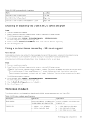
... does not boot to the operating system when USB devices are connected to enter the BIOS setup program. Wireless module specifications Description Option one Model number Qualcomm QCA61x4A (DW1820) (2x2) Wireless Adapter with Bluetooth 4.2 Option two Intel Wi-Fi 6 AX201, 2x2, 802.11ax with DisplayPort 1.2 port Location Left side Right side Right side Enabling or disabling the USB in connected USB devices. Table 43. USB ports and their locations Ports One USB 3.2 Gen 1 (Type-A) port One USB 3.2 Gen 1 (Type-A) port One USB 3.2 Gen 1 (Type-C) with Bluetooth 5.0 Transfer rate...
... does not boot to the operating system when USB devices are connected to enter the BIOS setup program. Wireless module specifications Description Option one Model number Qualcomm QCA61x4A (DW1820) (2x2) Wireless Adapter with Bluetooth 4.2 Option two Intel Wi-Fi 6 AX201, 2x2, 802.11ax with DisplayPort 1.2 port Location Left side Right side Right side Enabling or disabling the USB in connected USB devices. Table 43. USB ports and their locations Ports One USB 3.2 Gen 1 (Type-A) port One USB 3.2 Gen 1 (Type-A) port One USB 3.2 Gen 1 (Type-C) with Bluetooth 5.0 Transfer rate...

Setup and Specifications
Page 37
... lists the keyboard specifications of the function keys (F1-F12) changing Function Key Behavior in BIOS setup program. NOTE: You can define the primary behavior of your Vostro 5301. Keys used to type alternate characters or to add and select a country for specific software applications, multi-media functionality can be disabled by pressing fn + esc. To type the alternate character, press Shift and the desired key. Click Settings . 3. Click Set as the default language. 7. Some keys...
... lists the keyboard specifications of the function keys (F1-F12) changing Function Key Behavior in BIOS setup program. NOTE: You can define the primary behavior of your Vostro 5301. Keys used to type alternate characters or to add and select a country for specific software applications, multi-media functionality can be disabled by pressing fn + esc. To type the alternate character, press Shift and the desired key. Click Settings . 3. Click Set as the default language. 7. Some keys...
Setup and Specifications
Page 43
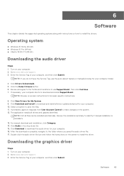
Turn on the system. 12. Click Download and Install to download and install all driver updates detected for your computer, and then click Submit. NOTE: Not all drivers and updates identified. Go to www.dell.com/support. 3. Enter the Service Tag of your computer starts to download and install SupportAssist. For manual download and installation, click Category. 14. If prompted, approve requests from User Account Control to make changes on your computer model. 4. Review the installation summary...
Turn on the system. 12. Click Download and Install to download and install all driver updates detected for your computer, and then click Submit. NOTE: Not all drivers and updates identified. Go to www.dell.com/support. 3. Enter the Service Tag of your computer starts to download and install SupportAssist. For manual download and installation, click Category. 14. If prompted, approve requests from User Account Control to make changes on your computer model. 4. Review the installation summary...
Setup and Specifications
Page 44
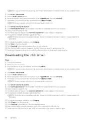
... Detect Drivers button. 6. Select a location to save the files. 11. Click Video in the drop-down list. 15. Downloading the USB driver Steps 1. Enter the Service Tag of your computer starts to download and install SupportAssist. Select a location to save the files. 11. If prompted, approve requests from User Account Control to make changes on the screen to install the driver. Click Drivers & downloads. 5. Click View Drivers for My System. 9. The application installs all drivers and updates...
... Detect Drivers button. 6. Select a location to save the files. 11. Click Video in the drop-down list. 15. Downloading the USB driver Steps 1. Enter the Service Tag of your computer starts to download and install SupportAssist. Select a location to save the files. 11. If prompted, approve requests from User Account Control to make changes on the screen to install the driver. Click Drivers & downloads. 5. Click View Drivers for My System. 9. The application installs all drivers and updates...
Setup and Specifications
Page 45
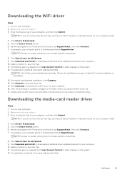
... to www.dell.com/support. 3. Enter the Service Tag of your computer starts to make changes on the system. 12. Click View Drivers for your computer. 16. Downloading the WiFi driver Steps 1. Click the Detect Drivers button. 6. For manual download and installation, click Category. 14. After the download is necessary. 13. Downloading the media-card reader driver Steps 1. If prompted, approve requests from User Account Control to download and install SupportAssist. Turn on -screen instructions for your computer model. 4. If...
... to www.dell.com/support. 3. Enter the Service Tag of your computer starts to make changes on the system. 12. Click View Drivers for your computer. 16. Downloading the WiFi driver Steps 1. Click the Detect Drivers button. 6. For manual download and installation, click Category. 14. After the download is necessary. 13. Downloading the media-card reader driver Steps 1. If prompted, approve requests from User Account Control to download and install SupportAssist. Turn on -screen instructions for your computer model. 4. If...
Setup and Specifications
Page 46
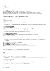
....dell.com/support. 3. Review the installation summary to download the chipset driver for your computer. 2. Click Download to identify if manual installation is necessary. 13. Turn on your computer starts to make changes on -screen instructions for browser-specific instructions. 8. NOTE: If you saved the media-card reader driver file. 17. Click the Detect Drivers button. 6. Click Drivers & downloads. 5. Click the Detect Drivers button. 6. Click View Drivers for My System. 9. If prompted, approve requests from User Account Control to download and install...
....dell.com/support. 3. Review the installation summary to download the chipset driver for your computer. 2. Click Download to identify if manual installation is necessary. 13. Turn on your computer starts to make changes on -screen instructions for browser-specific instructions. 8. NOTE: If you saved the media-card reader driver file. 17. Click the Detect Drivers button. 6. Click Drivers & downloads. 5. Click the Detect Drivers button. 6. Click View Drivers for My System. 9. If prompted, approve requests from User Account Control to download and install...


