Setup and Quick Reference Guide
Page 31
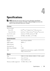
Processor Processor types: Vostro 420: Vostro 220, 220s: Level 2 (L2) cache Front side bus Intel® Core™2 Quad, Core™2 Duo processors Intel Core™2 Duo, Celeron®, Pentium® processors minimum 512 KB, maximum 12 MB 800 MHz, 1066 MHz, or 1333 MHz System Information Chipset RAID support DMA channels Interrupt levels BIOS chip (...regarding the configuration of 10/100/1000 Mbps communication Memory Type Memory connectors Memory modules supported DDR2 800 MHz SDRAM (DDR2 667 MHz capable) Vostro 420: four Vostro 220/220s: two 512 MB, 1 GB, or 2 GB Specifications 31
Processor Processor types: Vostro 420: Vostro 220, 220s: Level 2 (L2) cache Front side bus Intel® Core™2 Quad, Core™2 Duo processors Intel Core™2 Duo, Celeron®, Pentium® processors minimum 512 KB, maximum 12 MB 800 MHz, 1066 MHz, or 1333 MHz System Information Chipset RAID support DMA channels Interrupt levels BIOS chip (...regarding the configuration of 10/100/1000 Mbps communication Memory Type Memory connectors Memory modules supported DDR2 800 MHz SDRAM (DDR2 667 MHz capable) Vostro 420: four Vostro 220/220s: two 512 MB, 1 GB, or 2 GB Specifications 31
Setup and Quick Reference Guide
Page 32
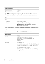
...). Memory (continued) Minimum memory 512 MB Maximum memory 4 GB NOTE: Due to the unique architecture of the Intel Core2 Quad processor, your system board and power supply must be included when upgrading processors. Audio Type Realtek ALC662 (5.1 Channel audio) Expansion Bus Bus type Bus speed PCI 2.3 PCI Express 2.0 (PCIe-x16) from G45...
...). Memory (continued) Minimum memory 512 MB Maximum memory 4 GB NOTE: Due to the unique architecture of the Intel Core2 Quad processor, your system board and power supply must be included when upgrading processors. Audio Type Realtek ALC662 (5.1 Channel audio) Expansion Bus Bus type Bus speed PCI 2.3 PCI Express 2.0 (PCIe-x16) from G45...

Setup and Quick Reference Guide
Page 36
... board cannot start initialization (see "Power Problems" on green light - Connectors (continued) Front panel audio HDA header Processor Memory Power 12V Power one 10-pin connector one 775-pin connector Vostro 420: four 240-pin connectors Vostro 220/220s: two 240-pin connectors one 4-pin connector one 24-pin connector Controls and Lights Front...
... board cannot start initialization (see "Power Problems" on green light - Connectors (continued) Front panel audio HDA header Processor Memory Power 12V Power one 10-pin connector one 775-pin connector Vostro 420: four 240-pin connectors Vostro 220/220s: two 240-pin connectors one 4-pin connector one 24-pin connector Controls and Lights Front...
Setup and Quick Reference Guide
Page 47
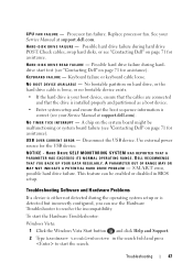
... click Help and Support. 2 Type hardware troubleshooter in BIOS setup. Troubleshooting 47 See your Service Manual at support.dell.com. NOTICE - Replace processor fan. Possible hard drive failure during harddrive start the search. No bootable partition on page 71 for assistance. Disconnect... you can be malfunctioning or system board failure (see your Service Manual at support.dell.com). Possible hard drive failure during hard drive POST. CPU FAN FAILURE - Processor fan failure. HARD DRIVE SELF MONITORING SYSTEM HAS REPORTED THAT A PARAMETER HAS EXCEEDED ...
... click Help and Support. 2 Type hardware troubleshooter in BIOS setup. Troubleshooting 47 See your Service Manual at support.dell.com. NOTICE - Replace processor fan. Possible hard drive failure during harddrive start the search. No bootable partition on page 71 for assistance. Disconnect... you can be malfunctioning or system board failure (see your Service Manual at support.dell.com). Possible hard drive failure during hard drive POST. CPU FAN FAILURE - Processor fan failure. HARD DRIVE SELF MONITORING SYSTEM HAS REPORTED THAT A PARAMETER HAS EXCEEDED ...

Setup and Quick Reference Guide
Page 51
...8226; Ensure that shipped with your Service Manual at www.dell.com/regulatory_compliance. Troubleshooting 51 The computer is receiving electrical power, a device might be malfunctioning or incorrectly installed. • Ensure that the processor power cable is securely connected to the system board power connector... (see your Service Manual at support.dell.com). • Ensure that the main power cable and the front panel ...
...8226; Ensure that shipped with your Service Manual at www.dell.com/regulatory_compliance. Troubleshooting 51 The computer is receiving electrical power, a device might be malfunctioning or incorrectly installed. • Ensure that the processor power cable is securely connected to the system board power connector... (see your Service Manual at support.dell.com). • Ensure that the main power cable and the front panel ...
Setup and Quick Reference Guide
Page 75
... and lights, 36 drives, 34 environmental, 38 expansion bus, 32 memory, 31 physical, 37 power, 37 processor, 31 system information, 31 video, 32 support, 65 contacting Dell, 71 DellConnect, 66 online services, 66 regional, 66 technical support and customer service, 66 support information, 8..., 62 T Terms and Conditions, 8 transferring information to a new computer, 17 troubleshooting, 8, 39 blue screen, 54 computer not responding, 52 Dell Diagnostics, 48 error messages, 41 memory, 51 power, 50 power light conditions, 50 power lights, 39 program crashes, 52 programs and Windows compatibility...
... and lights, 36 drives, 34 environmental, 38 expansion bus, 32 memory, 31 physical, 37 power, 37 processor, 31 system information, 31 video, 32 support, 65 contacting Dell, 71 DellConnect, 66 online services, 66 regional, 66 technical support and customer service, 66 support information, 8..., 62 T Terms and Conditions, 8 transferring information to a new computer, 17 troubleshooting, 8, 39 blue screen, 54 computer not responding, 52 Dell Diagnostics, 48 error messages, 41 memory, 51 power, 50 power light conditions, 50 power lights, 39 program crashes, 52 programs and Windows compatibility...

Service Manual
Page 1
... without the written permission of this document to refer to either trademarks or registered trademarks of Dell Inc.; Dell™ Vostro™ 420/220/220s Service Manual Troubleshooting Working on Your Computer Computer Cover Bezel Chassis Support Bracket PCI and... PCI Express Cards Drives I/O Panel Fan Processor Heat Sink/Fan Assembly Memory Module(s) Power Supply Coin-Cell Battery System Board Processor System Setup Program Contacting Dell...
... without the written permission of this document to refer to either trademarks or registered trademarks of Dell Inc.; Dell™ Vostro™ 420/220/220s Service Manual Troubleshooting Working on Your Computer Computer Cover Bezel Chassis Support Bracket PCI and... PCI Express Cards Drives I/O Panel Fan Processor Heat Sink/Fan Assembly Memory Module(s) Power Supply Coin-Cell Battery System Board Processor System Setup Program Contacting Dell...

Service Manual
Page 13
.... Push the release lever down and then press it has had sufficient time to Contents Page Processor Dell™ Vostro™ 420/220/220s Service Manual Removing the Processor Replacing the Processor CAUTION: Before working inside the socket or allow any of the computer. NOTICE: You must ...position the processor correctly in the socket to avoid permanent damage to release it from the retention hook that ...
.... Push the release lever down and then press it has had sufficient time to Contents Page Processor Dell™ Vostro™ 420/220/220s Service Manual Removing the Processor Replacing the Processor CAUTION: Before working inside the socket or allow any of the computer. NOTICE: You must ...position the processor correctly in the socket to avoid permanent damage to release it from the retention hook that ...

Service Manual
Page 14
...seated and secure. 11. NOTICE: Ensure that you apply new thermal grease. NOTICE: Socket pins are delicate. Replace the processor heat sink/fan assembly (see Replacing the Processor Heat Sink/Fan Assembly). NOTE: Ensure that the tab on Your Computer. NOTICE: To avoid damage, ensure that the... release lever fully and ensure that it will be underneath the retention latch when the release lever is fully seated. 6. Unpack the new processor, being careful not to the top of the heat sink. New thermal grease is critical for ensuring adequate thermal bonding, which is positioned ...
...seated and secure. 11. NOTICE: Ensure that you apply new thermal grease. NOTICE: Socket pins are delicate. Replace the processor heat sink/fan assembly (see Replacing the Processor Heat Sink/Fan Assembly). NOTE: Ensure that the tab on Your Computer. NOTICE: To avoid damage, ensure that the... release lever fully and ensure that it will be underneath the retention latch when the release lever is fully seated. 6. Unpack the new processor, being careful not to the top of the heat sink. New thermal grease is critical for ensuring adequate thermal bonding, which is positioned ...

Service Manual
Page 31
... rubber bushings (4) 2 heat sink/fan assembly 4 system board fan connector 6 captive screws (4) Back to Contents Page Processor Heat Sink/Fan Assembly Dell™ Vostro™ 420/220/220s Service Manual Removing the Processor Heat Sink/Fan Assembly Replacing the Processor Heat Sink/Fan Assembly CAUTION: Before working inside your computer, read the safety information that it...
... rubber bushings (4) 2 heat sink/fan assembly 4 system board fan connector 6 captive screws (4) Back to Contents Page Processor Heat Sink/Fan Assembly Dell™ Vostro™ 420/220/220s Service Manual Removing the Processor Heat Sink/Fan Assembly Replacing the Processor Heat Sink/Fan Assembly CAUTION: Before working inside your computer, read the safety information that it...

Service Manual
Page 32
Replacing the Processor Heat Sink/Fan Assembly NOTICE: Unless a new heat sink is correctly seated and secure. 4. Follow the procedure in After Working on the system board. 1 Phillips ... connector 6 captive screws (4) 3. Apply thermal solution to Contents Page NOTICE: Ensure that the assembly is required for the new processor, reuse the original heat sink/fan assembly when you replace the processor. 1. Back to the heat sink as needed. 2. Align the four captive screws on the heat sink/fan assembly with the...
Replacing the Processor Heat Sink/Fan Assembly NOTICE: Unless a new heat sink is correctly seated and secure. 4. Follow the procedure in After Working on the system board. 1 Phillips ... connector 6 captive screws (4) 3. Apply thermal solution to Contents Page NOTICE: Ensure that the assembly is required for the new processor, reuse the original heat sink/fan assembly when you replace the processor. 1. Back to the heat sink as needed. 2. Align the four captive screws on the heat sink/fan assembly with the...

Service Manual
Page 35
... System Board Components). 4. Grasp the module and pull it from Dell. Replacing or Adding a Memory Module NOTICE: Do not install ECC memory modules. Follow the procedures in DIMM connectors 3 and 4. The recommended memory configurations for Vostro 420 are: 1) A pair of matched memory modules installed in DIMM ...-6400 (DDR2 800-MHz) memory modules, the modules function at www.dell.com/regulatory_compliance. If the module is difficult to remove, gently ease the module back and forth to the processor, before you purchased the new modules from the connector. NOTICE: If...
... System Board Components). 4. Grasp the module and pull it from Dell. Replacing or Adding a Memory Module NOTICE: Do not install ECC memory modules. Follow the procedures in DIMM connectors 3 and 4. The recommended memory configurations for Vostro 420 are: 1) A pair of matched memory modules installed in DIMM ...-6400 (DDR2 800-MHz) memory modules, the modules function at www.dell.com/regulatory_compliance. If the module is difficult to remove, gently ease the module back and forth to the processor, before you purchased the new modules from the connector. NOTICE: If...

Service Manual
Page 42
...: The procedure for removing and replacing the system board is for the Vostro 420, Vostro 220, and Vostro 220s computers; Remove the chassis support bracket (see the Regulatory Compliance Homepage at www.dell.com/regulatory_compliance. If the system board is extremely fragile. Remove the processor heat sink/fan assembly (see Removing a PCI or PCI Express Card...
...: The procedure for removing and replacing the system board is for the Vostro 420, Vostro 220, and Vostro 220s computers; Remove the chassis support bracket (see the Regulatory Compliance Homepage at www.dell.com/regulatory_compliance. If the system board is extremely fragile. Remove the processor heat sink/fan assembly (see Removing a PCI or PCI Express Card...

Service Manual
Page 43
... replace and tighten all screws properly may not provide adequate grounding of the chassis. 2. Install the memory modules onto the system board (see Replacing the Processor). Install the processor onto the system board (see Replacing or Adding a Memory Module). Align the holes of the system board with a new system board: a.
... replace and tighten all screws properly may not provide adequate grounding of the chassis. 2. Install the memory modules onto the system board (see Replacing the Processor). Install the processor onto the system board (see Replacing or Adding a Memory Module). Align the holes of the system board with a new system board: a.
Service Manual
Page 44
Install the processor heat sink/fan assembly (see Installing a PCI or PCI Express Card). 10. Connect the power supply cables to the system board (see System Board Components ... cables to ensure that they are secure. Follow the procedure in After Working on the system board. 12. Connect all expansion cards (see Replacing the Processor Heat Sink/Fan Assembly). 5. Connect any additional cables to help identify connectors on Your Computer. See System Board Components to the system board as required...
Install the processor heat sink/fan assembly (see Installing a PCI or PCI Express Card). 10. Connect the power supply cables to the system board (see System Board Components ... cables to ensure that they are secure. Follow the procedure in After Working on the system board. 12. Connect all expansion cards (see Replacing the Processor Heat Sink/Fan Assembly). 5. Connect any additional cables to help identify connectors on Your Computer. See System Board Components to the system board as required...
Service Manual
Page 46
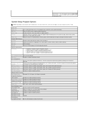
... -0; Legacy LAN; USB-CDROM; Disabled (Disabled by default All Error; Displays current date and time settings. All; Identifies whether the computer's processor supports Hyper-Threading and lists the processor type, processor bus speed, processor ID, clock speed, and L2 cache. CDROM; Indicates amount of installed memory, memory speed, channel mode (dual or single), and...
... -0; Legacy LAN; USB-CDROM; Disabled (Disabled by default All Error; Displays current date and time settings. All; Identifies whether the computer's processor supports Hyper-Threading and lists the processor type, processor bus speed, processor ID, clock speed, and L2 cache. CDROM; Indicates amount of installed memory, memory speed, channel mode (dual or single), and...

Service Manual
Page 51
...If the power light is blue and the computer is working inside your location, if applicable. ¡ Ensure that the processor power cable is securely connected to the same electrical outlet Beep Codes Your computer may emit a series of beeps during ...the power light is in standby mode. l Eliminate interference. Run the Dell Diagnostics to Contents Page Troubleshooting Dell™ Vostro™ 420/220/220s Service Manual Tools Dell Diagnostics Solving Problems Dell Technical Update Service Dell Support Utility Tools Power Lights CAUTION: Before working by testing it with your...
...If the power light is blue and the computer is working inside your location, if applicable. ¡ Ensure that the processor power cable is securely connected to the same electrical outlet Beep Codes Your computer may emit a series of beeps during ...the power light is in standby mode. l Eliminate interference. Run the Dell Diagnostics to Contents Page Troubleshooting Dell™ Vostro™ 420/220/220s Service Manual Tools Dell Diagnostics Solving Problems Dell Technical Update Service Dell Support Utility Tools Power Lights CAUTION: Before working by testing it with your...
Service Manual
Page 52
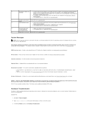
... error - Possible system board failure or RTC battery low. Replace the battery (see Processor Heat Sink/Fan Assembly). NOTICE - CPU fan failure - Processor heat sink/fan failure. System Messages NOTE: If the message you back up your computer (see Contacting Dell). Hard-disk read failure - A chip on the system board might be enabled...
... error - Possible system board failure or RTC battery low. Replace the battery (see Processor Heat Sink/Fan Assembly). NOTICE - CPU fan failure - Processor heat sink/fan failure. System Messages NOTE: If the message you back up your computer (see Contacting Dell). Hard-disk read failure - A chip on the system board might be enabled...

Service Manual
Page 61
... is not responding - The computer is steady amber - l Ensure that all memory modules (see the Regulatory Compliance Homepage at www.dell.com/regulatory_compliance. See the printer documentation for cable connection information. Click Start® Control Panel® Printers and Other Hardware® View... installed printers or fax printers. 2. l Ensure that the processor power cable is turned on the back of the computer and the electrical outlet. NOTE: If you need technical assistance for your computer....
... is not responding - The computer is steady amber - l Ensure that all memory modules (see the Regulatory Compliance Homepage at www.dell.com/regulatory_compliance. See the printer documentation for cable connection information. Click Start® Control Panel® Printers and Other Hardware® View... installed printers or fax printers. 2. l Ensure that the processor power cable is turned on the back of the computer and the electrical outlet. NOTE: If you need technical assistance for your computer....

Service Manual
Page 69
... ports (2) and ESATA connector 29 chassis fan connector 30 Display Port 31 video (VGA) and parallel ports 32 PS/2 mouse and keyboard connectors Vostro 220 1 power connector (PWR2) 2 processor heat sink/fan assembly power 4 main power connector (PWR1) 5 serial ATA drive connector (SATA2) 7 serial ATA drive connector (SATA3) 8 serial ATA drive connector... I/O panel) 15 audio connector (AUDIO1) (from front I/O panel) 18 PCI Express x16 connector (PCIE_x16) 21 one LAN and two USB ports 24 video connector (VGA) Vostro 220s
... ports (2) and ESATA connector 29 chassis fan connector 30 Display Port 31 video (VGA) and parallel ports 32 PS/2 mouse and keyboard connectors Vostro 220 1 power connector (PWR2) 2 processor heat sink/fan assembly power 4 main power connector (PWR1) 5 serial ATA drive connector (SATA2) 7 serial ATA drive connector (SATA3) 8 serial ATA drive connector... I/O panel) 15 audio connector (AUDIO1) (from front I/O panel) 18 PCI Express x16 connector (PCIE_x16) 21 one LAN and two USB ports 24 video connector (VGA) Vostro 220s


