Setup and Quick Reference Guide
Page 4
Vostro 220s Back View 28 Vostro 220s Back Panel Connectors 29 4 Specifications 31 5 Troubleshooting 39 Tools 39 Power Lights 39 Beep Codes 39 Error Messages 41 System Messages 46 Troubleshooting Software and Hardware Problems 47 Dell Diagnostics 48 Troubleshooting Tips 50 Power Problems 50 Memory Problems 51 Lockups and Software Problems 52 Dell Technical Update Service 54 Dell Support Utility 55 6 Reinstalling Software 57 Drivers 57 Identifying Drivers 57 Reinstalling Drivers and Utilities 58 4 Contents
Vostro 220s Back View 28 Vostro 220s Back Panel Connectors 29 4 Specifications 31 5 Troubleshooting 39 Tools 39 Power Lights 39 Beep Codes 39 Error Messages 41 System Messages 46 Troubleshooting Software and Hardware Problems 47 Dell Diagnostics 48 Troubleshooting Tips 50 Power Problems 50 Memory Problems 51 Lockups and Software Problems 52 Dell Technical Update Service 54 Dell Support Utility 55 6 Reinstalling Software 57 Drivers 57 Identifying Drivers 57 Reinstalling Drivers and Utilities 58 4 Contents

Setup and Quick Reference Guide
Page 12
4 Connect the modem. 5 Connect the power cable(s). 12 Setting Up Your Computer
4 Connect the modem. 5 Connect the power cable(s). 12 Setting Up Your Computer
Setup and Quick Reference Guide
Page 13
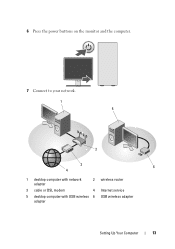
6 Press the power buttons on the monitor and the computer. 7 Connect to your network. 1 5 2 3 6 4 1 desktop computer with network adapter 2 wireless router 3 cable or DSL modem 4 Internet service 5 desktop computer with USB wireless 6 USB wireless adapter adapter Setting Up Your Computer 13
6 Press the power buttons on the monitor and the computer. 7 Connect to your network. 1 5 2 3 6 4 1 desktop computer with network adapter 2 wireless router 3 cable or DSL modem 4 Internet service 5 desktop computer with USB wireless 6 USB wireless adapter adapter Setting Up Your Computer 13

Setup and Quick Reference Guide
Page 21
About Your Computer Vostro 420 Front View 1 2 3 4 5 6 10 7 8 9 1 optical drive 3 optional optical-drive bays (2) 5 microphone connector 7 headphone connector 9 drive-activity light 2 drive bay front panel (open) 4 USB 2.0 connectors (4) 6 IEEE 1394 connector (optional) 8 power button, power light 10 media card reader (optional) About Your Computer 21
About Your Computer Vostro 420 Front View 1 2 3 4 5 6 10 7 8 9 1 optical drive 3 optional optical-drive bays (2) 5 microphone connector 7 headphone connector 9 drive-activity light 2 drive bay front panel (open) 4 USB 2.0 connectors (4) 6 IEEE 1394 connector (optional) 8 power button, power light 10 media card reader (optional) About Your Computer 21

Setup and Quick Reference Guide
Page 22
Vostro 420 Back View 1 2 7 6 5 3 4 1 power cord connector 3 security cable/padlock rings 5 back-panel connectors 7 voltage selector switch 2 power-supply vent 4 expansion card slots 6 power-supply light 22 About Your Computer
Vostro 420 Back View 1 2 7 6 5 3 4 1 power cord connector 3 security cable/padlock rings 5 back-panel connectors 7 voltage selector switch 2 power-supply vent 4 expansion card slots 6 power-supply light 22 About Your Computer
Setup and Quick Reference Guide
Page 24
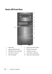
Vostro 220 Front View 1 2 3 4 5 10 6 7 8 9 1 optical drive 3 optional optical-drive bay 5 IEEE 1394 connector (optional) 7 microphone connector 9 drive-activity light 2 drive bay front panel (open) 4 USB 2.0 connectors (4) 6 headphone connector 8 power button, power light 10 media card reader (optional) 24 About Your Computer
Vostro 220 Front View 1 2 3 4 5 10 6 7 8 9 1 optical drive 3 optional optical-drive bay 5 IEEE 1394 connector (optional) 7 microphone connector 9 drive-activity light 2 drive bay front panel (open) 4 USB 2.0 connectors (4) 6 headphone connector 8 power button, power light 10 media card reader (optional) 24 About Your Computer
Setup and Quick Reference Guide
Page 25
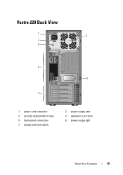
Vostro 220 Back View 1 2 7 6 5 3 4 1 power cord connector 3 security cable/padlock rings 5 back-panel connectors 7 voltage selector switch 2 power-supply vent 4 expansion card slots 6 power-supply light About Your Computer 25
Vostro 220 Back View 1 2 7 6 5 3 4 1 power cord connector 3 security cable/padlock rings 5 back-panel connectors 7 voltage selector switch 2 power-supply vent 4 expansion card slots 6 power-supply light About Your Computer 25
Setup and Quick Reference Guide
Page 27
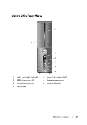
Vostro 220s Front View 1 7 1 media card reader (optional) 3 USB 2.0 connectors (2) 5 microphone connector 7 optical drive 2 3 4 5 6 2 power button, power light 4 headphone connector 6 drive-activity light About Your Computer 27
Vostro 220s Front View 1 7 1 media card reader (optional) 3 USB 2.0 connectors (2) 5 microphone connector 7 optical drive 2 3 4 5 6 2 power button, power light 4 headphone connector 6 drive-activity light About Your Computer 27
Setup and Quick Reference Guide
Page 28
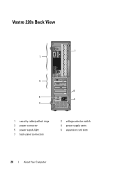
Vostro 220s Back View 1 7 6 2 5 3 4 1 security cable/padlock rings 3 power connector 5 power supply light 7 back-panel connectors 2 voltage selector switch 4 power supply vents 6 expansion card slots 28 About Your Computer
Vostro 220s Back View 1 7 6 2 5 3 4 1 security cable/padlock rings 3 power connector 5 power supply light 7 back-panel connectors 2 voltage selector switch 4 power supply vents 6 expansion card slots 28 About Your Computer
Setup and Quick Reference Guide
Page 32
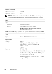
Memory (continued) Minimum memory 512 MB Maximum memory 4 GB NOTE: Due to the unique architecture of the Intel Core2 Quad processor, your system board and power supply must be included when upgrading processors. Audio Type Realtek ALC662 (5.1 Channel audio) Expansion Bus Bus type Bus speed PCI 2.3 PCI Express 2.0 (PCIe-x16) from ...
Memory (continued) Minimum memory 512 MB Maximum memory 4 GB NOTE: Due to the unique architecture of the Intel Core2 Quad processor, your system board and power supply must be included when upgrading processors. Audio Type Realtek ALC662 (5.1 Channel audio) Expansion Bus Bus type Bus speed PCI 2.3 PCI Express 2.0 (PCIe-x16) from ...

Setup and Quick Reference Guide
Page 36
...no light) - The computer is reading data from or writing data to the network. Rear of computer: Power button push button Power light blue light - off - solid blue for power-on page 50). System is in sleep state; A blinking blue light indicates the computer is not detecting... adapter) network and the computer. Connectors (continued) Front panel audio HDA header Processor Memory Power 12V Power one 10-pin connector one 775-pin connector Vostro 420: four 240-pin connectors Vostro 220/220s: two 240-pin connectors one 4-pin connector one 24-pin connector Controls and...
...no light) - The computer is reading data from or writing data to the network. Rear of computer: Power button push button Power light blue light - off - solid blue for power-on page 50). System is in sleep state; A blinking blue light indicates the computer is not detecting... adapter) network and the computer. Connectors (continued) Front panel audio HDA header Processor Memory Power 12V Power one 10-pin connector one 775-pin connector Vostro 420: four 240-pin connectors Vostro 220/220s: two 240-pin connectors one 4-pin connector one 24-pin connector Controls and...
Setup and Quick Reference Guide
Page 37
Power DC power supply: Wattage Vostro 420: 350 W Vostro 220: 300 W Vostro 220s: 250 W Maximum heat dissipation for 350 W power supply, 1194 BTU/hr (MHD) for 300 W power supply, 1023 BTU/hr for important voltage setting information) Vostro 420: 115/230 VAC, 50/60 Hz, 8A/4A Vostro 220: 115/230 VAC, 50/60 Hz, 7A/4A Vostro 220s: 115/230 VAC, 50...
Power DC power supply: Wattage Vostro 420: 350 W Vostro 220: 300 W Vostro 220s: 250 W Maximum heat dissipation for 350 W power supply, 1194 BTU/hr (MHD) for 300 W power supply, 1023 BTU/hr for important voltage setting information) Vostro 420: 115/230 VAC, 50/60 Hz, 8A/4A Vostro 220: 115/230 VAC, 50/60 Hz, 7A/4A Vostro 220s: 115/230 VAC, 50...

Setup and Quick Reference Guide
Page 39
...of beeps during start-up if the monitor cannot display errors or problems. This series of repetitive three short beeps. Tools Power Lights The two-color power-button light located on the front of the computer turns on and blinks or remains solid to resume normal operation. Troubleshooting ...For additional safety best practices information, see the Regulatory Compliance Homepage at www.dell.com/regulatory_compliance. This beep code tells you begin any of the procedures in standby mode. Press a key on . • If the power light is blinking blue, the computer is steady amber, there may be...
...of beeps during start-up if the monitor cannot display errors or problems. This series of repetitive three short beeps. Tools Power Lights The two-color power-button light located on the front of the computer turns on and blinks or remains solid to resume normal operation. Troubleshooting ...For additional safety best practices information, see the Regulatory Compliance Homepage at www.dell.com/regulatory_compliance. This beep code tells you begin any of the procedures in standby mode. Press a key on . • If the power light is blinking blue, the computer is steady amber, there may be...
Setup and Quick Reference Guide
Page 47
.... Possible hard drive failure during the operating system setup or is detected but incorrectly configured, you can be malfunctioning or system board failure (see "Contacting Dell" on page 71 for assistance). N O T I M E R T I C K I V E P R O B L E M - HARD DRIVE SELF MONITORING SYSTEM HAS REPORTED THAT A PARAMETER HAS EXCEEDED ITS NORMAL OPERATING RANGE. A ... is either not detected during hard drive POST. No bootable partition on page 71 for the USB device. Use external power source for assistance. Troubleshooting 47 USB OVER CURRENT ERROR - KEYBOARD FAILURE -
.... Possible hard drive failure during the operating system setup or is detected but incorrectly configured, you can be malfunctioning or system board failure (see "Contacting Dell" on page 71 for assistance). N O T I M E R T I C K I V E P R O B L E M - HARD DRIVE SELF MONITORING SYSTEM HAS REPORTED THAT A PARAMETER HAS EXCEEDED ITS NORMAL OPERATING RANGE. A ... is either not detected during hard drive POST. No bootable partition on page 71 for the USB device. Use external power source for assistance. Troubleshooting 47 USB OVER CURRENT ERROR - KEYBOARD FAILURE -
Setup and Quick Reference Guide
Page 50
... device is working by testing it with your Dell computer to the Windows Classic view. This message may not apply if you set your computer. For additional safety best practices information, see the program documentation. IF T H E POWER LIGHT IS O F F - Power Problems CAUTION: Before you begin any power strips being used are plugged into an...
... device is working by testing it with your Dell computer to the Windows Classic view. This message may not apply if you set your computer. For additional safety best practices information, see the program documentation. IF T H E POWER LIGHT IS O F F - Power Problems CAUTION: Before you begin any power strips being used are plugged into an...

Setup and Quick Reference Guide
Page 51
... standby mode. For additional safety best practices information, see your Service Manual at www.dell.com/regulatory_compliance. Troubleshooting 51 The computer is receiving electrical power, a device might be malfunctioning or incorrectly installed. • Ensure that the processor power cable is a power problem, a device may be malfunctioning or incorrectly installed. • Remove and then reinstall...
... standby mode. For additional safety best practices information, see your Service Manual at www.dell.com/regulatory_compliance. Troubleshooting 51 The computer is receiving electrical power, a device might be malfunctioning or incorrectly installed. • Ensure that the processor power cable is a power problem, a device may be malfunctioning or incorrectly installed. • Remove and then reinstall...
Setup and Quick Reference Guide
Page 52
...Reseat the memory modules (see your Service Manual at support.dell.com). • Ensure that the memory you are using to ensure that your computer is supported by your computer. The computer does not start up ENSURE THAT THE POWER CABLE IS FIRMLY CONNECTED TO THE COMPUTER AND TO THE ...ELECTRICAL OUTLET The computer stops responding NOTICE: You may lose data if you are not using is successfully communicating with the memory. • Run the Dell Diagnostics (see "Dell Diagnostics" on page 31. &#...
...Reseat the memory modules (see your Service Manual at support.dell.com). • Ensure that the memory you are using to ensure that your computer is supported by your computer. The computer does not start up ENSURE THAT THE POWER CABLE IS FIRMLY CONNECTED TO THE COMPUTER AND TO THE ...ELECTRICAL OUTLET The computer stops responding NOTICE: You may lose data if you are not using is successfully communicating with the memory. • Run the Dell Diagnostics (see "Dell Diagnostics" on page 31. &#...
Setup and Quick Reference Guide
Page 53
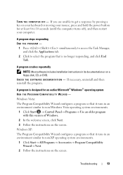
... program that it runs in an environment similar to 10 seconds (until the computer turns off), and then restart your mouse, press and hold the power button for an earlier Microsoft® Windows® operating system RUN THE PROGRAM COMPATIBILITY WIZARD - A program is no longer responding, and click End Task. TURN...
... program that it runs in an environment similar to 10 seconds (until the computer turns off), and then restart your mouse, press and hold the power button for an earlier Microsoft® Windows® operating system RUN THE PROGRAM COMPATIBILITY WIZARD - A program is no longer responding, and click End Task. TURN...

Setup and Quick Reference Guide
Page 54
...CDs, or DVDs • Save and close any open files or programs and shut down your computer through the Start menu Dell Technical Update Service The Dell Technical Update service provides proactive e-mail notification of software and hardware updates for information. • Ensure that the program is compatible... meets the minimum hardware requirements needed to 10 seconds (until the computer turns off), and then restart your mouse, press and hold the power button for content, format, and how frequently you are unable to get a response by pressing a key on your computer. The service ...
...CDs, or DVDs • Save and close any open files or programs and shut down your computer through the Start menu Dell Technical Update Service The Dell Technical Update service provides proactive e-mail notification of software and hardware updates for information. • Ensure that the program is compatible... meets the minimum hardware requirements needed to 10 seconds (until the computer turns off), and then restart your mouse, press and hold the power button for content, format, and how frequently you are unable to get a response by pressing a key on your computer. The service ...

Setup and Quick Reference Guide
Page 65
... Getting Help Obtaining Assistance CAUTION: If you need to remove the computer cover, first disconnect the computer power and modem cables from a telephone at Dell Support (support.dell.com) for a more extensive list of online services available at or near the affected computer so that..." on page 71. For additional safety best practices information, see "Contacting Dell" on page 70. 4 Use Dell's extensive suite of Dell Support online. 5 If the preceding steps have an Express Service Code, open the Dell Accessories folder, double-click the Express Service Code icon, and follow the ...
... Getting Help Obtaining Assistance CAUTION: If you need to remove the computer cover, first disconnect the computer power and modem cables from a telephone at Dell Support (support.dell.com) for a more extensive list of online services available at or near the affected computer so that..." on page 71. For additional safety best practices information, see "Contacting Dell" on page 70. 4 Use Dell's extensive suite of Dell Support online. 5 If the preceding steps have an Express Service Code, open the Dell Accessories folder, double-click the Express Service Code icon, and follow the ...


