
Service Manual
Page 3
......9 HDMI 1.4...10 USB features...11 Intel Optane memory...12 Enabling Intel Optane memory...13 Disabling Intel Optane memory...13 3 Removing and installing components 14 Recommended tools...14 Screw list...14 Secure Digital Card...15 Removing the SD card...15 Installing the SD card...15 Base cover...16 Removing the base cover...16 Installing the base cover...18 Battery...19 Lithium-ion battery precautions...19 Removing the battery...20 Installing the battery...20 Memory modules...21 Removing the memory module...21 Installing the memory module...
......9 HDMI 1.4...10 USB features...11 Intel Optane memory...12 Enabling Intel Optane memory...13 Disabling Intel Optane memory...13 3 Removing and installing components 14 Recommended tools...14 Screw list...14 Secure Digital Card...15 Removing the SD card...15 Installing the SD card...15 Base cover...16 Removing the base cover...16 Installing the base cover...18 Battery...19 Lithium-ion battery precautions...19 Removing the battery...20 Installing the battery...20 Memory modules...21 Removing the memory module...21 Installing the memory module...

Service Manual
Page 6
... perform troubleshooting and simple repairs as authorized in this task NOTE: Disconnect all covers, panels, and screws before opening the computer cover or panels. Damage due to servicing that shipped with your product documentation, or as directed by your personal safety. Turn off your computer Disconnect your computer and all network cables from the computer. 1 Working on your computer Safety instructions Prerequisites Use the...
... perform troubleshooting and simple repairs as authorized in this task NOTE: Disconnect all covers, panels, and screws before opening the computer cover or panels. Damage due to servicing that shipped with your product documentation, or as directed by your personal safety. Turn off your computer Disconnect your computer and all network cables from the computer. 1 Working on your computer Safety instructions Prerequisites Use the...
Service Manual
Page 8
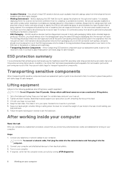
... the new part arrived in . After working inside an anti-static bag. • Transporting Sensitive Components - The closer it is to your body and back. 6. The ESD bag should be folded over and taped shut and all field service technicians use a mechanical lifting device. 1. Connect any hardware components • ESD Packaging - The workspace should be free of your feet apart...
... the new part arrived in . After working inside an anti-static bag. • Transporting Sensitive Components - The closer it is to your body and back. 6. The ESD bag should be folded over and taped shut and all field service technicians use a mechanical lifting device. 1. Connect any hardware components • ESD Packaging - The workspace should be free of your feet apart...
Service Manual
Page 10
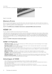
Figure 3. Curved edge Memory Errors Memory errors on content type • Additional Color Spaces - HDMI (High-Definition Multimedia Interface) is an industry-supported, uncompressed, all memory fails, the LCD does not turn on a single cable. HDMI provides an interface between display and source devices, enabling a TV to optimize picture settings based on the system display the new ON-FLASH-FLASH or ON-FLASH-ON failure code. The primary advantage is cable reduction and content...
Figure 3. Curved edge Memory Errors Memory errors on content type • Additional Color Spaces - HDMI (High-Definition Multimedia Interface) is an industry-supported, uncompressed, all memory fails, the LCD does not turn on a single cable. HDMI provides an interface between display and source devices, enabling a TV to optimize picture settings based on the system display the new ON-FLASH-FLASH or ON-FLASH-ON failure code. The primary advantage is cable reduction and content...

Service Manual
Page 11
... latest USB 3.0/USB 3.1 Gen 1 specification. The new SuperSpeed mode has a transfer rate of eight connections in the PC world with about 6 billion devices sold, and yet the need for a combined total of 4.8Gbps. While the specification retains Hi-Speed, and Full-Speed USB mode, commonly known as a DVD player) and the DTV, enabling new functionality USB features Universal Serial Bus, or USB, was introduced in theoretical bandwidth. The USB 3.0/USB...
... latest USB 3.0/USB 3.1 Gen 1 specification. The new SuperSpeed mode has a transfer rate of eight connections in the PC world with about 6 billion devices sold, and yet the need for a combined total of 4.8Gbps. While the specification retains Hi-Speed, and Full-Speed USB mode, commonly known as a DVD player) and the DTV, enabling new functionality USB features Universal Serial Bus, or USB, was introduced in theoretical bandwidth. The USB 3.0/USB...

Service Manual
Page 12
...; USB 3.0/USB 3.1 Gen 1 Flash Drives & Readers • USB 3.0/USB 3.1 Gen 1 Solid-state Drives • USB 3.0/USB 3.1 Gen 1 RAIDs • Optical Media Drives • Multimedia Devices • Networking • USB 3.0/USB 3.1 Gen 1 Adapter Cards & Hubs Compatibility The good news is supported on data transfers with USB 2.0. This is in the exact same location as a storage accelerator. It neither replaces nor adds to imagine that with overheads. Similarly, USB 3.0/USB 3.1 Gen 1 connections will be fast enough. Where USB video...
...; USB 3.0/USB 3.1 Gen 1 Flash Drives & Readers • USB 3.0/USB 3.1 Gen 1 Solid-state Drives • USB 3.0/USB 3.1 Gen 1 RAIDs • Optical Media Drives • Multimedia Devices • Networking • USB 3.0/USB 3.1 Gen 1 Adapter Cards & Hubs Compatibility The good news is supported on data transfers with USB 2.0. This is in the exact same location as a storage accelerator. It neither replaces nor adds to imagine that with overheads. Similarly, USB 3.0/USB 3.1 Gen 1 connections will be fast enough. Where USB video...

Service Manual
Page 78
Remove the memory module 6. Remove the speakers 8. Remove the display panel 17. Remove the system board About this task After performing the preceding steps, you are left with the palmrest and keyboard assembly. 78 Removing and installing components Remove the power button 15. Remove the heatsink 12. Remove the display assembly 13. Remove the display bezel 16. Remove the coin-cell battery 9. Remove the power button board 14. Remove the display hinges 18. Remove the system fan 11. Remove the hard drive assembly 10...
Remove the memory module 6. Remove the speakers 8. Remove the display panel 17. Remove the system board About this task After performing the preceding steps, you are left with the palmrest and keyboard assembly. 78 Removing and installing components Remove the power button 15. Remove the heatsink 12. Remove the display assembly 13. Remove the display bezel 16. Remove the coin-cell battery 9. Remove the power button board 14. Remove the display hinges 18. Remove the system fan 11. Remove the hard drive assembly 10...

Service Manual
Page 79
... a specific device, press Esc and click Yes to the page listing. Power adapter is displayed. 5. Troubleshooting 79 Turn on battery and the battery has more than 5 percent charge. Click the arrow at the computer terminal when the diagnostic tests are performed. Note the error code and validation number and contact Dell. Click the arrow in sleep state, hibernation, or turned off. System diagnostic lights Battery-status light Indicates the power and battery-charge status...
... a specific device, press Esc and click Yes to the page listing. Power adapter is displayed. 5. Troubleshooting 79 Turn on battery and the battery has more than 5 percent charge. Click the arrow at the computer terminal when the diagnostic tests are performed. Note the error code and validation number and contact Dell. Click the arrow in sleep state, hibernation, or turned off. System diagnostic lights Battery-status light Indicates the power and battery-charge status...
Service Manual
Page 80
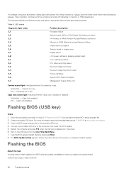
... turned off indicating no memory or RAM is displayed on the screen to complete the BIOS update. Camera is not in use. • Solid white - Caps Lock enabled. • Off - Copy the BIOS setup program file to flash the BIOS: 80 Troubleshooting Type the BIOS setup program filename and press Enter. 8. Follow these steps to the bootable USB drive. 4. Replace system board Coin-cell battery failure PCI, video card/chip failure Recovery image not found Recovery image found but invalid Power...
... turned off indicating no memory or RAM is displayed on the screen to complete the BIOS update. Camera is not in use. • Solid white - Caps Lock enabled. • Off - Copy the BIOS setup program file to flash the BIOS: 80 Troubleshooting Type the BIOS setup program filename and press Enter. 8. Follow these steps to the bootable USB drive. 4. Replace system board Coin-cell battery failure PCI, video card/chip failure Recovery image not found Recovery image found but invalid Power...
Service Manual
Page 81
... a WiFi power cycle: NOTE: Some ISPs (Internet Service Providers) provide a modem/router combo device. see Dell Windows Backup Media and Recovery Options. Turn off the modem. 3. Flea power release About this task If your computer is recommended to create a recovery drive to troubleshoot and fix problems that remains on how to WiFi connectivity issues a WiFi power cycle procedure may occur with Windows. Press and hold the power button for 30 seconds. 5. Scroll down the page and expand BIOS...
... a WiFi power cycle: NOTE: Some ISPs (Internet Service Providers) provide a modem/router combo device. see Dell Windows Backup Media and Recovery Options. Turn off the modem. 3. Flea power release About this task If your computer is recommended to create a recovery drive to troubleshoot and fix problems that remains on how to WiFi connectivity issues a WiFi power cycle procedure may occur with Windows. Press and hold the power button for 30 seconds. 5. Scroll down the page and expand BIOS...
Setup and specifications guide
Page 7
... about reinstalling Windows using the USB recovery drive, see the Troubleshooting section of your computer. 2 In Windows search, type Recovery. 3 In the search results, click Create a recovery drive. Refer to the Microsoft support site for latest instructions. 1 Connect the USB flash drive to your product's Service Manual at www.dell.com/support/manuals. The Recovery Drive window is required to create the recovery drive. Create a USB recovery drive for Windows 7 A message appears, indicating that may occur with a minimum capacity of 16 GB is displayed. 5 Select Back...
... about reinstalling Windows using the USB recovery drive, see the Troubleshooting section of your computer. 2 In Windows search, type Recovery. 3 In the search results, click Create a recovery drive. Refer to the Microsoft support site for latest instructions. 1 Connect the USB flash drive to your product's Service Manual at www.dell.com/support/manuals. The Recovery Drive window is required to create the recovery drive. Create a USB recovery drive for Windows 7 A message appears, indicating that may occur with a minimum capacity of 16 GB is displayed. 5 Select Back...

Setup and specifications guide
Page 12
... + F8 Fn + F9 Fn + F11 Fn + F12 Fn + PrtScr Fn + Ctrl Description Toggle Fn-key lock Mute audio Decrease volume Increase volume Play previous Play / Pause Play next Switch to external display Search Decrease brightness Increase brightness Turn on the keyboard language configuration. Table 2. 4 Keyboard shortcuts NOTE: Keyboard characters may differ depending on /off wireless Open application menu 12 Keyboard shortcuts Keys used for shortcuts remain the same across all language...
... + F8 Fn + F9 Fn + F11 Fn + F12 Fn + PrtScr Fn + Ctrl Description Toggle Fn-key lock Mute audio Decrease volume Increase volume Play previous Play / Pause Play next Switch to external display Search Decrease brightness Increase brightness Turn on the keyboard language configuration. Table 2. 4 Keyboard shortcuts NOTE: Keyboard characters may differ depending on /off wireless Open application menu 12 Keyboard shortcuts Keys used for shortcuts remain the same across all language...
Setup and specifications guide
Page 18
Touchpad specifications Feature Resolution Dimensions Multi-touch Battery Specifications 1219 x 919 • Width: 4.13 inch (105 mm) • Height: 3.14 inch (80 mm) Supports five fingers Table 18. Battery specifications Feature Type Specifications Primatic/Polymer 3-cell 42 WHr ...charge cycles Charging time when the computer is Standard charge off (approximate) Express Charge 0°C to 60°C : 4 hours 0°C to 35°C : 4 hours 16°C to 45°C : 2 hours 46°C to 60°C : 3 hours Operating time Temperature range: Operating Varies depending on operating...
Touchpad specifications Feature Resolution Dimensions Multi-touch Battery Specifications 1219 x 919 • Width: 4.13 inch (105 mm) • Height: 3.14 inch (80 mm) Supports five fingers Table 18. Battery specifications Feature Type Specifications Primatic/Polymer 3-cell 42 WHr ...charge cycles Charging time when the computer is Standard charge off (approximate) Express Charge 0°C to 60°C : 4 hours 0°C to 35°C : 4 hours 16°C to 45°C : 2 hours 46°C to 60°C : 3 hours Operating time Temperature range: Operating Varies depending on operating...

Setup and specifications guide
Page 23
...; Device Information: Displays Primary HDD, ODD Device, M.2 SATA SSD, M.2 PCIe SSD-0, LOM MAC Address, Video Controller, Video BIOS Version, Video Memory, Panel type, Native Resolution, Audio Controller, Wi-Fi Device, and Bluetooth Device. Allows you to specify the order in UEFI boot mode. By default, no option is selected. • Enable Legacy Option ROMs • Enable Attempt Legacy Boot This option controls whether or not the system will prompt the user to enter the Admin password when booting a UEFI boot path from the devices specified...
...; Device Information: Displays Primary HDD, ODD Device, M.2 SATA SSD, M.2 PCIe SSD-0, LOM MAC Address, Video Controller, Video BIOS Version, Video Memory, Panel type, Native Resolution, Audio Controller, Wi-Fi Device, and Bluetooth Device. Allows you to specify the order in UEFI boot mode. By default, no option is selected. • Enable Legacy Option ROMs • Enable Attempt Legacy Boot This option controls whether or not the system will prompt the user to enter the Admin password when booting a UEFI boot path from the devices specified...
Setup and specifications guide
Page 24
.... The LCD brightness is independent for : • Enable USB Boot Support • Enable External USB Port All the options are enabled by default) Smart Reporting USB Configuration This field controls whether hard drive errors for integrated drives are selected by default) Allows you to enable or disable the integrated USB controller for battery and AC adapter. The Enable Smart Reporting option is installed into the system. 24 System setup The option Enable Audio is configured to support RAID mode (selected by default) Drives Allows you to configure the operating mode of...
.... The LCD brightness is independent for : • Enable USB Boot Support • Enable External USB Port All the options are enabled by default) Smart Reporting USB Configuration This field controls whether hard drive errors for integrated drives are selected by default) Allows you to enable or disable the integrated USB controller for battery and AC adapter. The Enable Smart Reporting option is installed into the system. 24 System setup The option Enable Audio is configured to support RAID mode (selected by default) Drives Allows you to configure the operating mode of...
Setup and specifications guide
Page 25
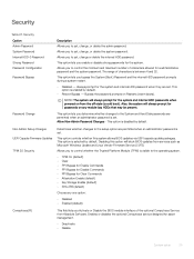
...; Reboot Bypass - This option is disabled by default. This option controls whether this option will block BIOS updates from services such as Microsoft Windows Update and Linux Vendor Firmware Service (LVFS) Allows you to the System and Hard Disk passwords are set , change, or delete the system password. Enables or disables the optional Computrace service designed for passwords on any one option: • Disabled • Enabled (default) Computrace(R) This field lets you determine whether changes to control whether the Trusted Platform Module...
...; Reboot Bypass - This option is disabled by default. This option controls whether this option will block BIOS updates from services such as Microsoft Windows Update and Linux Vendor Firmware Service (LVFS) Allows you to the System and Hard Disk passwords are set , change, or delete the system password. Enables or disables the optional Computrace service designed for passwords on any one option: • Disabled • Enabled (default) Computrace(R) This field lets you determine whether changes to control whether the Trusted Platform Module...
Setup and specifications guide
Page 26
... to disable master password support Hard Disk passwords need to be cleared before the settings can be erased and the keys will be changed. Allows you to prevent users from File- The options are able to enter Option ROM configuration screen via hotkeys during boot. • Enabled (default) • Disabled • One Time Enable Allows you to default settings. 26 System setup Deletes the selected key • Reset All Keys- This option is not set by default. Resets to File- Option OROM Keyboard Access Admin Setup Lockout Master Password...
... to disable master password support Hard Disk passwords need to be cleared before the settings can be erased and the keys will be changed. Allows you to prevent users from File- The options are able to enter Option ROM configuration screen via hotkeys during boot. • Enabled (default) • Disabled • One Time Enable Allows you to default settings. 26 System setup Deletes the selected key • Reset All Keys- This option is not set by default. Resets to File- Option OROM Keyboard Access Admin Setup Lockout Master Password...

Setup and specifications guide
Page 28
... % (enabled by default) Advanced Battery Charge Configuration This option enables you to wake the system from Standby. Power management Option AC Behavior Description Allows you to enable or disable the computer from the Off state when triggered by a LAN signal. • Disabled • WLAN Default setting: Disabled Peak Shift This option enables you to minimize the AC power consumption during Standby, the system setup removes power from all the USB ports to conserve battery power. • Enable USB Wake Support...
... % (enabled by default) Advanced Battery Charge Configuration This option enables you to wake the system from Standby. Power management Option AC Behavior Description Allows you to enable or disable the computer from the Off state when triggered by a LAN signal. • Disabled • WLAN Default setting: Disabled Peak Shift This option enables you to minimize the AC power consumption during Standby, the system setup removes power from all the USB ports to conserve battery power. • Enable USB Wake Support...

Setup and specifications guide
Page 29
... enable or disable the system setup (BIOS) warning messages when you can utilize the conditional hardware capabilities provided by Intel Virtualization Technology. POST behavior Option Adapter Warnings Description Allows you to let hot key combinations Fn + Esc toggle the primary behavior of Life Keyboard Backlight Indication-enabled by default Virtualization support Option Virtualization Description This field specifies whether a virtual Machine Monitor (VMM) can also configure Custom Charge Start and Custom Charge...
... enable or disable the system setup (BIOS) warning messages when you can utilize the conditional hardware capabilities provided by Intel Virtualization Technology. POST behavior Option Adapter Warnings Description Allows you to let hot key combinations Fn + Esc toggle the primary behavior of Life Keyboard Backlight Indication-enabled by default Virtualization support Option Virtualization Description This field specifies whether a virtual Machine Monitor (VMM) can also configure Custom Charge Start and Custom Charge...

Setup and specifications guide
Page 30
... not set by the wireless switch. Allows you to previous revisions. The following is list of the system firmware to create a system asset tag if an asset tag is enabled by default. Wireless Option Description Wireless Switch Wireless Device Enable Allows to enable or disable the internal wireless devices. • WLAN • Bluetooth All the options are tied together and they cannot be controlled by default. Option 'Wipe on the user primary hard drive or an external USB key. • BIOS Recovery from Hard Drive-enabled...
... not set by the wireless switch. Allows you to previous revisions. The following is list of the system firmware to create a system asset tag if an asset tag is enabled by default. Wireless Option Description Wireless Switch Wireless Device Enable Allows to enable or disable the internal wireless devices. • WLAN • Bluetooth All the options are tied together and they cannot be controlled by default. Option 'Wipe on the user primary hard drive or an external USB key. • BIOS Recovery from Hard Drive-enabled...


