
User Manual
Page 2
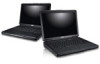
...optical drive 11. optical drive eject button 12. Secure Digital (SD) memory-card reader 16. touchpad disable LED 22. keyboard 23. power connector 3. powered USB 3.0 connector 7. headphone connector 2 fingerprint reader 13. hard disk status light 20. security cable slot 2. HDMI connector 6. microphone connector 9. network connector 9. power button Figure 2. USB 3.0 connector 10. cooling vents 5. touchpad buttons (2) 17. wireless status light 18. USB 3.0 connector 14. battery status light 19. Dell Instant Launch Manager 8. 7. USB 3.0 connector...
...optical drive 11. optical drive eject button 12. Secure Digital (SD) memory-card reader 16. touchpad disable LED 22. keyboard 23. power connector 3. powered USB 3.0 connector 7. headphone connector 2 fingerprint reader 13. hard disk status light 20. security cable slot 2. HDMI connector 6. microphone connector 9. network connector 9. power button Figure 2. USB 3.0 connector 10. cooling vents 5. touchpad buttons (2) 17. wireless status light 18. USB 3.0 connector 14. battery status light 19. Dell Instant Launch Manager 8. 7. USB 3.0 connector...

User Manual
Page 3
camera status light 4. display 5. network connector 9. optical drive eject button 12. power status light 21. camera 3. Windows Mobility Center 6. touchpad 15. wireless status light 18. hard disk status light 20. power button 3 keyboard 23. Vostro 3560 - Dell Support Center 7. optical drive 11. ExpressCard slot 14. Front View 1. Secure Digital (SD) memory-card reader 16. touchpad disable LED 22. battery status light 19. Dell Instant Launch Manager 8. USB 3.0 connectors (2) 10. Front And Back View Figure 3. microphone 2. touchpad buttons (2) 17....
camera status light 4. display 5. network connector 9. optical drive eject button 12. power status light 21. camera 3. Windows Mobility Center 6. touchpad 15. wireless status light 18. hard disk status light 20. power button 3 keyboard 23. Vostro 3560 - Dell Support Center 7. optical drive 11. ExpressCard slot 14. Front View 1. Secure Digital (SD) memory-card reader 16. touchpad disable LED 22. battery status light 19. Dell Instant Launch Manager 8. USB 3.0 connectors (2) 10. Front And Back View Figure 3. microphone 2. touchpad buttons (2) 17....

Owner's Manual
Page 3
... Card...9 Removing the Battery...9 Installing the Battery...10 Removing the ExpressCard...10 Installing the ExpressCard...10 Removing the Base Cover...10 Installing the Base Cover...12 Removing the Memory...12 Installing the Memory...12 Removing the Optical Drive...12 Installing the Optical Drive...14 Removing the Hard Drive...14 Installing the Hard Drive...16 Removing the Keyboard...16 Installing the Keyboard...18 Removing the Display Hinge Cover...18 Installing the Display Hinge Cover...19 Removing the Palmrest...19 Installing the Palmrest...24 Removing the ExpressCard Reader...24 Installing...
... Card...9 Removing the Battery...9 Installing the Battery...10 Removing the ExpressCard...10 Installing the ExpressCard...10 Removing the Base Cover...10 Installing the Base Cover...12 Removing the Memory...12 Installing the Memory...12 Removing the Optical Drive...12 Installing the Optical Drive...14 Removing the Hard Drive...14 Installing the Hard Drive...16 Removing the Keyboard...16 Installing the Keyboard...18 Removing the Display Hinge Cover...18 Installing the Display Hinge Cover...19 Removing the Palmrest...19 Installing the Palmrest...24 Removing the ExpressCard Reader...24 Installing...
Owner's Manual
Page 4
... Display Bracket...47 Installing the Display Bracket...49 Removing the Camera Module...50 Installing the Camera Module...50 3 System Setup...53 Boot Sequence...53 Navigation Keys...53 System Setup Options...54 Updating the BIOS ...58 System and Setup Password...58 Assigning a System Password and Setup Password 58 Deleting or Changing an Existing System and/or Setup Password 59 4 Diagnostics...61 Enhanced Pre-Boot System Assessment (ePSA) Diagnostics 61 Device Status Lights...61 Battery Status Lights...62 Diagnostic Beep Codes...62 5 Specifications...
... Display Bracket...47 Installing the Display Bracket...49 Removing the Camera Module...50 Installing the Camera Module...50 3 System Setup...53 Boot Sequence...53 Navigation Keys...53 System Setup Options...54 Updating the BIOS ...58 System and Setup Password...58 Assigning a System Password and Setup Password 58 Deleting or Changing an Existing System and/or Setup Password 59 4 Diagnostics...61 Enhanced Pre-Boot System Assessment (ePSA) Diagnostics 61 Device Status Lights...61 Battery Status Lights...62 Diagnostic Beep Codes...62 5 Specifications...

Owner's Manual
Page 5
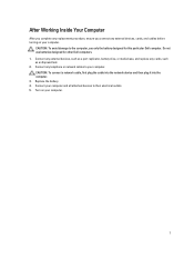
... only perform troubleshooting and simple repairs as authorized in reverse order. Do not touch the components or contacts on a card. Hold a card by its edges or by a certified service technician. Hold a component such as a connector on the back of the computer. As you begin working inside the computer. 1. If the computer is not covered by performing the removal procedure in...
... only perform troubleshooting and simple repairs as authorized in reverse order. Do not touch the components or contacts on a card. Hold a card by its edges or by a certified service technician. Hold a component such as a connector on the back of the computer. As you begin working inside the computer. 1. If the computer is not covered by performing the removal procedure in...

Owner's Manual
Page 6
... the operating system: - Press the power button to turn off . Remove any installed ExpressCards or Smart Cards from the electrical outlet before opening the display. Open the display. 10. CAUTION: To guard against electrical shock, always unplug your computer. 1. Shut down your computer, ground yourself by touching an unpainted metal surface, such as shown below, and then click Shut Down. - In Windows 7: Click Start...
... the operating system: - Press the power button to turn off . Remove any installed ExpressCards or Smart Cards from the electrical outlet before opening the display. Open the display. 10. CAUTION: To guard against electrical shock, always unplug your computer. 1. Shut down your computer, ground yourself by touching an unpainted metal surface, such as shown below, and then click Shut Down. - In Windows 7: Click Start...
Owner's Manual
Page 7
... connect a network cable, first plug the cable into the network device and then plug it into the computer. 3. Connect any telephone or network cables to your computer and all attached devices to the computer, use batteries designed for this particular Dell computer. Connect any external devices, such as a port replicator, battery slice, or media base, and replace any cards, such as an ExpressCard. 2. CAUTION: To avoid damage to their electrical outlets. 5. Turn...
... connect a network cable, first plug the cable into the network device and then plug it into the computer. 3. Connect any telephone or network cables to your computer and all attached devices to the computer, use batteries designed for this particular Dell computer. Connect any external devices, such as a port replicator, battery slice, or media base, and replace any cards, such as an ExpressCard. 2. CAUTION: To avoid damage to their electrical outlets. 5. Turn...

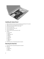
Owner's Manual
Page 12
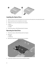
... Working Inside Your Computer. Installing the Memory 1. Remove the: a) battery b) base cover 3. Install the battery. 4. Lift and remove the memory module from the memory module until it on the computer and slide it pops-up. Insert and secure the memory module to the system board. 2. Pry the retention clips away from its connector. Removing the Optical Drive 1. Removing the Memory 1. Follow the procedures in Before Working Inside Your Computer. 2. Installing the Base Cover...
... Working Inside Your Computer. Installing the Memory 1. Remove the: a) battery b) base cover 3. Install the battery. 4. Lift and remove the memory module from the memory module until it on the computer and slide it pops-up. Insert and secure the memory module to the system board. 2. Pry the retention clips away from its connector. Removing the Optical Drive 1. Removing the Memory 1. Follow the procedures in Before Working Inside Your Computer. 2. Installing the Base Cover...
Owner's Manual
Page 14
Removing the Hard Drive 1. Remove the: a) battery b) base cover 3. Install the: a) base cover b) battery 5. Remove the screws that secure the optical drive to the computer. 4. Replace the optical-drive bracket and tighten the screws that secure the hard drive to the optical-drive bracket. 2. Slide the optical drive into the compartment on the chassis. 3. Follow the procedures in Before Working Inside Your Computer. 2. Follow the procedures in After Working Inside...
Removing the Hard Drive 1. Remove the: a) battery b) base cover 3. Install the: a) base cover b) battery 5. Remove the screws that secure the optical drive to the computer. 4. Replace the optical-drive bracket and tighten the screws that secure the hard drive to the optical-drive bracket. 2. Slide the optical drive into the compartment on the chassis. 3. Follow the procedures in Before Working Inside Your Computer. 2. Follow the procedures in After Working Inside...
Owner's Manual
Page 32
... and connect the LVDS and camera cable. 4. Install the: a) SD card reader b) palmrest c) display hinge cover d) keyboard e) hard drive f) optical drive g) base cover h) battery i) express card j) SD card 9. Remove the: a) SD card b) express card c) battery d) base cover 32 Connect the touchpad cable. 5. Follow the procedures in After Working Inside Your Computer. Align the system board to the chassis. 3. Follow the procedures in Before Working Inside Your Computer. 2. Tighten the screws to secure the system board to the port connectors...
... and connect the LVDS and camera cable. 4. Install the: a) SD card reader b) palmrest c) display hinge cover d) keyboard e) hard drive f) optical drive g) base cover h) battery i) express card j) SD card 9. Remove the: a) SD card b) express card c) battery d) base cover 32 Connect the touchpad cable. 5. Follow the procedures in After Working Inside Your Computer. Align the system board to the chassis. 3. Follow the procedures in Before Working Inside Your Computer. 2. Tighten the screws to secure the system board to the port connectors...
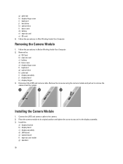
Owner's Manual
Page 50
...Install the: a) display bracket b) display bezel c) display assembly d) LAN board e) system board f) express card reader g) speakers 50 Connect the LVDS and camera cable to the display assembly. 3. Installing the Camera Module 1. Place the camera module to its original position and tighten the screw to secure it to the camera. 2. Follow the procedures in After Working Inside Your Computer. Disconnect the LVDS and camera cable. Removing the Camera Module 1. g) palmrest h) display hinge cover i) keyboard j) hard drive k) optical drive l) base cover m) battery n) express card...
...Install the: a) display bracket b) display bezel c) display assembly d) LAN board e) system board f) express card reader g) speakers 50 Connect the LVDS and camera cable to the display assembly. 3. Installing the Camera Module 1. Place the camera module to its original position and tighten the screw to secure it to the camera. 2. Follow the procedures in After Working Inside Your Computer. Disconnect the LVDS and camera cable. Removing the Camera Module 1. g) palmrest h) display hinge cover i) keyboard j) hard drive k) optical drive l) base cover m) battery n) express card...

Owner's Manual
Page 53
... the Dell logo appears, you can: • Access System Setup by pressing key • Bring up the one-time boot menu by pressing key The one-time boot menu displays the devices that you to bypass the System Setup‐defined boot device order and boot directly to a specific device (for example: optical drive or hard drive). Down arrow Moves to manage your computer security Boot Sequence Boot Sequence allows you make are : • Removable Drive (if...
... the Dell logo appears, you can: • Access System Setup by pressing key • Bring up the one-time boot menu by pressing key The one-time boot menu displays the devices that you to bypass the System Setup‐defined boot device order and boot directly to a specific device (for example: optical drive or hard drive). Down arrow Moves to manage your computer security Boot Sequence Boot Sequence allows you make are : • Removable Drive (if...
Owner's Manual
Page 55
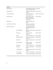
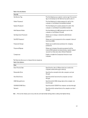
... Device AC Adapter Type Extended Memory System Memory Memory Speed Keyboard Type L2 Cache L3 Cache Displays the processor L2 cache size. Displays the model number and capacity of the AC adapter. Displays the type of the optical drive. Displays the memory installed on the computer. Advanced Options Advanced Intel SpeedStep Enable or disable the Intel Default: Enabled SpeedStep feature. Integrated NIC Enable or disable the power Default: Enabled supply to the on-board network card. USB Emulation Enable or disable the USB Default: Enabled emulation feature. Default: Disabled...
... Device AC Adapter Type Extended Memory System Memory Memory Speed Keyboard Type L2 Cache L3 Cache Displays the processor L2 cache size. Displays the model number and capacity of the AC adapter. Displays the type of the optical drive. Displays the memory installed on the computer. Advanced Options Advanced Intel SpeedStep Enable or disable the Intel Default: Enabled SpeedStep feature. Integrated NIC Enable or disable the power Default: Enabled supply to the on-board network card. USB Emulation Enable or disable the USB Default: Enabled emulation feature. Default: Disabled...
Owner's Manual
Page 56
... battery will be charged when connected to either ATA or AHCI. Default: Enabled The Security tab displays the security status and allows you enable or disable various on-board devices. Enables or disables fingerprint reader. Advanced SATA Operation Adapter Warnings Function Key Behavior Charger Behavior Battery Health Intel Rapid Start Technology Miscellaneous Devices External USB Ports Microphone Camera Media Card Reader Optical Drive Fingerprint Reader Boot Disable USB debug Internal Bluetooth Internal WLAN Internal WWAN Change the SATA controller Default: AHCI mode to an AC power...
... battery will be charged when connected to either ATA or AHCI. Default: Enabled The Security tab displays the security status and allows you enable or disable various on-board devices. Enables or disables fingerprint reader. Advanced SATA Operation Adapter Warnings Function Key Behavior Charger Behavior Battery Health Intel Rapid Start Technology Miscellaneous Devices External USB Ports Microphone Camera Media Card Reader Optical Drive Fingerprint Reader Boot Disable USB debug Internal Bluetooth Internal WLAN Internal WWAN Change the SATA controller Default: AHCI mode to an AC power...
Owner's Manual
Page 57
... hibernate state. (Default: Disabled) Enable or disable the Computrace feature on the computer's internal hard drive (HDD). Boot Options Boot Boot Priority Order Removable Drive Hard Disk Drives USB Storage Device CD/DVD/CD-RW Drive Network Specifies the order of different devices in which USB storage device the computer can boot through . Specifies which the computer will boot through . The Boot tab allows you to bypass the system password and the internal HDD password prompts during a system restart/ resume from System Setup. 57 Exit...
... hibernate state. (Default: Disabled) Enable or disable the Computrace feature on the computer's internal hard drive (HDD). Boot Options Boot Boot Priority Order Removable Drive Hard Disk Drives USB Storage Device CD/DVD/CD-RW Drive Network Specifies the order of different devices in which USB storage device the computer can boot through . Specifies which the computer will boot through . The Boot tab allows you to bypass the system password and the internal HDD password prompts during a system restart/ resume from System Setup. 57 Exit...
Owner's Manual
Page 58
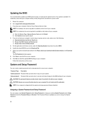
... 1. Restart the computer. 2. On the application and drivers screen, under the Operating System drop-down list, select BIOS. 6. If the Password Status is fully charged and connected to your computer. The File Download window appears. 8. Click Save to the BIOS settings of your system. For notebooks, ensure that your computer battery is Locked, you must enter to access and make changes to save the file on the bottom of...
... 1. Restart the computer. 2. On the application and drivers screen, under the Operating System drop-down list, select BIOS. 6. If the Password Status is fully charged and connected to your computer. The File Download window appears. 8. Click Save to the BIOS settings of your system. For notebooks, ensure that your computer battery is Locked, you must enter to access and make changes to save the file on the bottom of...

Owner's Manual
Page 61
... that inform you if tests are unable to fix the problem yourself, service and support personnel can use the diagnostics results to test only your hardware. If there are any issues, error codes are performed. 1. Note the error code and contact Dell. The ePSA is embedded with the BIOS and is displayed, listing all the detected devices. 4. Power-on when the computer reads or writes data...
... that inform you if tests are unable to fix the problem yourself, service and support personnel can use the diagnostics results to test only your hardware. If there are any issues, error codes are performed. 1. Note the error code and contact Dell. The ePSA is embedded with the BIOS and is displayed, listing all the detected devices. 4. Power-on when the computer reads or writes data...

Owner's Manual
Page 62
... Beep Codes The following steps 62 Table 7. Turns on when wireless networking is attached to an electrical outlet, the battery light operates as follows: Alternately blinking amber light and white An unauthenticated or unsupported non-Dell AC adapter is enabled. Light off Battery in progress of failure. Diagnostic Beep Codes Beep 1 Description BIOS ROM checksum in full charge mode with AC adapter present. Battery Status Lights If the computer is connected to light your...
... Beep Codes The following steps 62 Table 7. Turns on when wireless networking is attached to an electrical outlet, the battery light operates as follows: Alternately blinking amber light and white An unauthenticated or unsupported non-Dell AC adapter is enabled. Light off Battery in progress of failure. Diagnostic Beep Codes Beep 1 Description BIOS ROM checksum in full charge mode with AC adapter present. Battery Status Lights If the computer is connected to light your...

Owner's Manual
Page 65
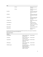
... series • Intel Core i7 series up to view information about your computer, click Start (Start icon) → Help and Support, and then select the option to 6 MB Table 10. Memory Feature Memory connector Memory capacity Memory type Minimum memory Maximum memory Description two SODIMM slots 2 GB, 4 GB, 6 GB, or 8 GB DDR3 SDRAM (1333 MHz and 1600 MHz) 2 GB 8 GB Table 11. Table 8. Audio Feature Type Controller: Vostro...
... series • Intel Core i7 series up to view information about your computer, click Start (Start icon) → Help and Support, and then select the option to 6 MB Table 10. Memory Feature Memory connector Memory capacity Memory type Minimum memory Maximum memory Description two SODIMM slots 2 GB, 4 GB, 6 GB, or 8 GB DDR3 SDRAM (1333 MHz and 1600 MHz) 2 GB 8 GB Table 11. Table 8. Audio Feature Type Controller: Vostro...

Owner's Manual
Page 66
... 4000 nVidia GeForce GT 630M AMD Radeon HD7670M Description HD 720P 1280 x 720 pixels at 30 FPS Description 10/100/1000 Mbps Ethernet LAN • internal WLAN Video Feature Video type Data bus: UMA Discrete: Vostro 3460 Vostro 3560 Video controller: UMA Discrete: Vostro 3460 Vostro 3560 Table 13. Camera Feature Camera Resolution Video Resolution (maximum) Table 14. Feature Vostro 3460 / Vostro 3560 Stereo conversion Interface: Internal External Speakers Volume controls Table 12.
... 4000 nVidia GeForce GT 630M AMD Radeon HD7670M Description HD 720P 1280 x 720 pixels at 30 FPS Description 10/100/1000 Mbps Ethernet LAN • internal WLAN Video Feature Video type Data bus: UMA Discrete: Vostro 3460 Vostro 3560 Video controller: UMA Discrete: Vostro 3460 Vostro 3560 Table 13. Camera Feature Camera Resolution Video Resolution (maximum) Table 14. Feature Vostro 3460 / Vostro 3560 Stereo conversion Interface: Internal External Speakers Volume controls Table 12.


