
Desktop Service Manual
Page 3
... 1: Working inside your computer 6 Before working inside your computer...6 Safety instructions...6 Electrostatic discharge-ESD protection...7 ESD field service kit ...7 Transporting sensitive components...8 After working inside your computer...9 Chapter 2: Removing and installing components 10 Recommended tools...10 Screw list...10 Major components of Vostro 3020 Tower Desktop 11 Left-side cover...12 Removing the left-side cover...12 Installing the left-side cover...13 Left-side cover...14 Removing the left-side cover...14 Installing...
... 1: Working inside your computer 6 Before working inside your computer...6 Safety instructions...6 Electrostatic discharge-ESD protection...7 ESD field service kit ...7 Transporting sensitive components...8 After working inside your computer...9 Chapter 2: Removing and installing components 10 Recommended tools...10 Screw list...10 Major components of Vostro 3020 Tower Desktop 11 Left-side cover...12 Removing the left-side cover...12 Installing the left-side cover...13 Left-side cover...14 Removing the left-side cover...14 Installing...
Desktop Service Manual
Page 4
... and setup password...70 Assigning a system setup password...70 Deleting or changing an existing system setup password 71 Real Time Clock (RTC) reset...71 Clearing BIOS (System Setup) and System passwords 72 Updating the BIOS...72 Updating the BIOS in Windows...72 Updating the BIOS using the USB drive in Windows 72 Updating the BIOS from the F12 One-Time boot menu 73 Chapter 5: Troubleshooting...74 Locate the Service Tag or Express Service Code of your Dell computer 74 SupportAssist diagnostics...74 System diagnostic lights...74...
... and setup password...70 Assigning a system setup password...70 Deleting or changing an existing system setup password 71 Real Time Clock (RTC) reset...71 Clearing BIOS (System Setup) and System passwords 72 Updating the BIOS...72 Updating the BIOS in Windows...72 Updating the BIOS using the USB drive in Windows 72 Updating the BIOS from the F12 One-Time boot menu 73 Chapter 5: Troubleshooting...74 Locate the Service Tag or Express Service Code of your Dell computer 74 SupportAssist diagnostics...74 System diagnostic lights...74...

Desktop Service Manual
Page 6
... Start > Power > Shut down your computer. Remove any media card and optical disc from all open files and exit all power sources before opening the computer cover or panels. For more safety best practices, see the documentation of the computer. NOTE: If you must disengage before disconnecting the cable. 6 Working inside your computer Disconnect your computer and all attached network devices and peripherals, such as keyboard, mouse, and monitor from...
... Start > Power > Shut down your computer. Remove any media card and optical disc from all open files and exit all power sources before opening the computer cover or panels. For more safety best practices, see the documentation of the computer. NOTE: If you must disengage before disconnecting the cable. 6 Working inside your computer Disconnect your computer and all attached network devices and peripherals, such as keyboard, mouse, and monitor from...

Desktop Service Manual
Page 7
... percent of damage to avoid bending the connector pins. Components of an ESD field service kit The components of memory integrity, intermittent memory errors, etc. The physical connection of catastrophic failure is temporarily placed on the mat. Never Working inside your hand, on it in the system, or inside a bag. ● Wrist Strap and Bonding Wire - As the industry pushes for missing...
... percent of damage to avoid bending the connector pins. Components of an ESD field service kit The components of memory integrity, intermittent memory errors, etc. The physical connection of catastrophic failure is temporarily placed on the mat. Never Working inside your hand, on it in the system, or inside a bag. ● Wrist Strap and Bonding Wire - As the industry pushes for missing...
Desktop Service Manual
Page 8
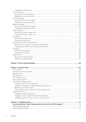
... centimeters away from internal parts that is free of clutter and large enough to use anti-static bags for a desktop or portable environment. Transporting sensitive components When transporting ESD sensitive components such as replacement parts or parts to be removed from packaging only at a minimum, test once per week. ● ESD Wrist Strap Tester - Lifting equipment Adhere to Dell, it is...
... centimeters away from internal parts that is free of clutter and large enough to use anti-static bags for a desktop or portable environment. Transporting sensitive components When transporting ESD sensitive components such as replacement parts or parts to be removed from packaging only at a minimum, test once per week. ● ESD Wrist Strap Tester - Lifting equipment Adhere to Dell, it is...

Desktop Service Manual
Page 9
... 1. Replace all attached devices to their electrical outlets. 5. Connect your computer and all screws and ensure that you removed before working on your computer. 4. Working inside your computer may severely damage your computer. Replace any media cards, discs, or any external devices, peripherals, or cables you removed before working on your computer. After working inside your computer About this task CAUTION: Leaving stray or loose screws inside your computer 9 Turn...
... 1. Replace all attached devices to their electrical outlets. 5. Connect your computer and all screws and ensure that you removed before working on your computer. 4. Working inside your computer may severely damage your computer. Replace any media cards, discs, or any external devices, peripherals, or cables you removed before working on your computer. After working inside your computer About this task CAUTION: Leaving stray or loose screws inside your computer 9 Turn...

Desktop Service Manual
Page 12
... coverages purchased by the customer. Contact your computer. 5. 2230 solid-state drive 6. graphics card 11. wireless card 15. system board 8. memory module NOTE: Dell provides a list of the left -side cover Prerequisites 1. Follow the procedure in Before working inside your Dell sales representative for the original system configuration purchased. hard drive 12. media-card reader 7. processor 16. About this task The following image(s) indicate the location of components and their part numbers for purchase...
... coverages purchased by the customer. Contact your computer. 5. 2230 solid-state drive 6. graphics card 11. wireless card 15. system board 8. memory module NOTE: Dell provides a list of the left -side cover Prerequisites 1. Follow the procedure in Before working inside your Dell sales representative for the original system configuration purchased. hard drive 12. media-card reader 7. processor 16. About this task The following image(s) indicate the location of components and their part numbers for purchase...

Desktop Service Manual
Page 51
... (SATA 1) 13. PCI-32 slot (SLOT 4, optional) NOTE: Not available for china The following image indicates the slots and connectors on your system board. 1. Remove the fan and heat-sink assembly. 13. optical-drive data cable connector (SATA 3) 11. M.2 2230/2280 solid-state drive slot 15. system-board power cable connector 6. About this task The following image(s) indicate the location of the system board and provides a visual representation of the removal procedure. M.2 2230 wireless-card slot 12. memory-module slots 5. hard-drive data cable connector (SATA 0, boot drive...
... (SATA 1) 13. PCI-32 slot (SLOT 4, optional) NOTE: Not available for china The following image indicates the slots and connectors on your system board. 1. Remove the fan and heat-sink assembly. 13. optical-drive data cable connector (SATA 3) 11. M.2 2230/2280 solid-state drive slot 15. system-board power cable connector 6. About this task The following image(s) indicate the location of the system board and provides a visual representation of the removal procedure. M.2 2230 wireless-card slot 12. memory-module slots 5. hard-drive data cable connector (SATA 0, boot drive...
Desktop Service Manual
Page 59
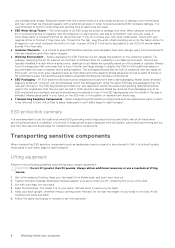
... system. NOTE: For the standard graphics browser only. Expands or collapses a drop-down the BIOS Setup program screen information for the following purposes: ● Get information about the hardware installed in your computer, such as the amount of RAM and the size of the hard drive. ● Change the system configuration information. ● Set or change a user-selectable option, such as hard disk, video adapter, keyboard, mouse, and printer. Pressing Esc...
... system. NOTE: For the standard graphics browser only. Expands or collapses a drop-down the BIOS Setup program screen information for the following purposes: ● Get information about the hardware installed in your computer, such as the amount of RAM and the size of the hard drive. ● Change the system configuration information. ● Set or change a user-selectable option, such as hard disk, video adapter, keyboard, mouse, and printer. Pressing Esc...
Desktop Service Manual
Page 60
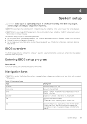
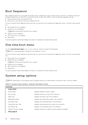
... boot sequence screen also displays the option to a specific device (for example: optical drive or hard drive). The one -time boot menu displays the devices that you to bypass the System Setup-defined boot device order and boot directly to access the System Setup screen. System setup options-System information menu Overview Vostro 3020 BIOS Version Displays the BIOS version number. Ownership Date Displays the ownership date of the computer. Express Service Code Displays the express service code of the computer. One time boot menu To enter one time boot menu, turn...
... boot sequence screen also displays the option to a specific device (for example: optical drive or hard drive). The one -time boot menu displays the devices that you to bypass the System Setup-defined boot device order and boot directly to access the System Setup screen. System setup options-System information menu Overview Vostro 3020 BIOS Version Displays the BIOS version number. Ownership Date Displays the ownership date of the computer. Express Service Code Displays the express service code of the computer. One time boot menu To enter one time boot menu, turn...

Desktop Service Manual
Page 61
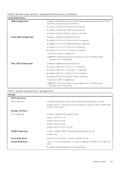
... code. Memory Speed Displays the memory speed. Memory Technology Displays the technology used . DIMM 1 Size Displays the DIMM 1 memory size. Wi-Fi Device Displays the wireless device information of the computer. Processor L2 Cache Displays the Processor L2 Cache size. Processor L3 Cache Displays the Processor L2 Cache size. MEMORY Memory Installed Displays the total computer memory installed. DEVICES Video Controller Displays the video controller type of this computer. System setup options-Boot Configuration menu Boot Configuration Boot Sequence Boot Mode...
... code. Memory Speed Displays the memory speed. Memory Technology Displays the technology used . DIMM 1 Size Displays the DIMM 1 memory size. Wi-Fi Device Displays the wireless device information of the computer. Processor L2 Cache Displays the Processor L2 Cache size. Processor L3 Cache Displays the Processor L2 Cache size. MEMORY Memory Installed Displays the total computer memory installed. DEVICES Video Controller Displays the video controller type of this computer. System setup options-Boot Configuration menu Boot Configuration Boot Sequence Boot Mode...

Desktop Service Manual
Page 62
... reset all integrated audio controller. You can switch between 12-hour and 24-hour clock. Default: OFF Secure Boot Mode Modifies the behavior of UEFI driver signatures. Custom Mode Key Management Allows for normal operation of key database. ● Save to File will save the key to their default settings. Table 6. Changes to be modified. Audio Enables or disables all four keys to a user-selected file. ● Replace from a user- Default: OFF NOTE: If Custom Mode...
... reset all integrated audio controller. You can switch between 12-hour and 24-hour clock. Default: OFF Secure Boot Mode Modifies the behavior of UEFI driver signatures. Custom Mode Key Management Allows for normal operation of key database. ● Save to File will save the key to their default settings. Table 6. Changes to be modified. Audio Enables or disables all four keys to a user-selected file. ● Replace from a user- Default: OFF NOTE: If Custom Mode...
Desktop Service Manual
Page 63
... Enables or disables booting from USB mass storage devices such as external hard drive, optical drive, and USB drive. By default, Enable USB Boot Support is selected. By default, Front Port 3 (Top Left) is selected. By default, Rear Port 1 (Top Left)* is selected. By default, Rear Port 3 (Bottom Left) is selected. Storage device is selected. Turn on or off all media cards, or enable or disable the media card in the BIOS setup irrespective of the integrated storage device controller. By default, Enable Front USB Ports is configured to support RAID. (Intel® Rapid Restore...
... Enables or disables booting from USB mass storage devices such as external hard drive, optical drive, and USB drive. By default, Enable USB Boot Support is selected. By default, Front Port 3 (Top Left) is selected. By default, Rear Port 1 (Top Left)* is selected. By default, Rear Port 3 (Bottom Left) is selected. Storage device is selected. Turn on or off all media cards, or enable or disable the media card in the BIOS setup irrespective of the integrated storage device controller. By default, Enable Front USB Ports is configured to support RAID. (Intel® Rapid Restore...

Desktop Service Manual
Page 64
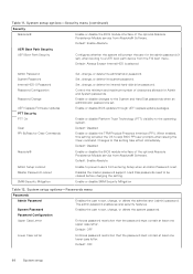
... Enable or disable UEFI Network Stack. Brightness on battery power Sets the screen brightness when the computer is selected. By default, Enable with PXE is selected. Auto Mode will extract Boot URL from Standby, Hibernation, or Power Off state. System setup options-Power menu Power USB Wake Support Enable USB Wake Support Enables USB devices like a mouse or keyboard to wake the system from the Dynamic Host Configuration Protocol (DHCP). Table 10. System setup options-Display menu Display Primary Display Video Primary Display Set or change the primary video controller...
... Enable or disable UEFI Network Stack. Brightness on battery power Sets the screen brightness when the computer is selected. By default, Enable with PXE is selected. Auto Mode will extract Boot URL from Standby, Hibernation, or Power Off state. System setup options-Power menu Power USB Wake Support Enable USB Wake Support Enables USB devices like a mouse or keyboard to wake the system from the Dynamic Host Configuration Protocol (DHCP). Table 10. System setup options-Display menu Display Primary Display Video Primary Display Set or change the primary video controller...

Desktop Service Manual
Page 65
... this setting take effect immediately. The operating system makes use of power. Any data on the next reboot. Default: Power OFF is handshaking between the device and PCI Express hub to skip BIOS PPI user prompts when issuing the Clear command. Changes to protect the secure environment crated by the device. Active State Power Management ASPM Configures the Active State Power Management (ASPM) level. Changes to the motherboard on the storage device(s) cannot...
... this setting take effect immediately. The operating system makes use of power. Any data on the next reboot. Default: Power OFF is handshaking between the device and PCI Express hub to skip BIOS PPI user prompts when issuing the Clear command. Changes to protect the secure environment crated by the device. Active State Power Management ASPM Configures the Active State Power Management (ASPM) level. Changes to the motherboard on the storage device(s) cannot...
Desktop Service Manual
Page 66
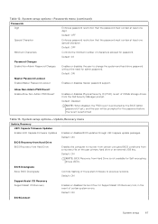
...to set . Control the minimum and maximum number of the optional Absolute Persistence Module service from the F12 boot menu. Enable or disable BIOS updates through UEFI capsule update packages. Disables the master password support. System setup options-Passwords menu Passwords Admin Password System Password Password Configuration Upper Case Letter Enables the user to a UEFI boot path device from Absolute® Software. The admin password enables several security features Enables the user to skip BIOS PPI user prompts when issuing the Clear command. Default: OFF Lower Case Letter...
...to set . Control the minimum and maximum number of the optional Absolute Persistence Module service from the F12 boot menu. Enable or disable BIOS updates through UEFI capsule update packages. Disables the master password support. System setup options-Passwords menu Passwords Admin Password System Password Password Configuration Upper Case Letter Enables the user to a UEFI boot path device from Absolute® Software. The admin password enables several security features Enables the user to skip BIOS PPI user prompts when issuing the Clear command. Default: OFF Lower Case Letter...
Desktop Service Manual
Page 67
... password. BIOS Downgrade Allow BIOS Downgrade Controls flashing of certain system errors. Default: 04 Password Changes Enable Non-Admin Password Changes Enables or disables the user to change the system and hard drive password without the need for Self-encrypting drives (SED). System setup options-Passwords menu (continued) Passwords Digit Enforces password restriction that the password must contain at least one digit. Default: ON NOTE: BIOS Recovery from a recovery file on the user primary hard drive or an external USB key. Default: OFF Special Character Enforces password...
... password. BIOS Downgrade Allow BIOS Downgrade Controls flashing of certain system errors. Default: 04 Password Changes Enable Non-Admin Password Changes Enables or disables the user to change the system and hard drive password without the need for Self-encrypting drives (SED). System setup options-Passwords menu (continued) Passwords Digit Enforces password restriction that the password must contain at least one digit. Default: ON NOTE: BIOS Recovery from a recovery file on the user primary hard drive or an external USB key. Default: OFF Special Character Enforces password...
Desktop Service Manual
Page 71
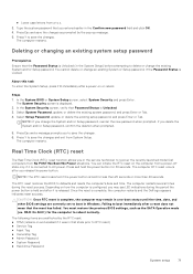
... RTC reset) ● Service Tag ● Asset Tag ● Ownership Tag ● Admin Password ● System Password ● Hard drive Password System setup 71 The computer RTC reset occurs after a power-on how the computer is configured, you entered earlier in that Password Status is displayed. 2. Press Y to recover the recently launched model Dell computers from No POST/No Boot/No Power situations. In the System BIOS or System Setup screen...
... RTC reset) ● Service Tag ● Asset Tag ● Ownership Tag ● Admin Password ● System Password ● Hard drive Password System setup 71 The computer RTC reset occurs after a power-on how the computer is configured, you entered earlier in that Password Status is displayed. 2. Press Y to recover the recently launched model Dell computers from No POST/No Boot/No Power situations. In the System BIOS or System Setup screen...
Desktop Service Manual
Page 72
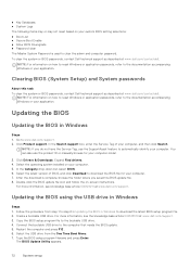
... the BIOS update file icon and follow the on-screen instructions. You can also use the SupportAssist feature to download the BIOS file for your computer model. 3. Click Drivers & Downloads. After the download is used to the computer that needs the BIOS update. 5. NOTE: For information on how to reset Windows or application passwords, refer to download the latest BIOS setup program file. 2. Updating the BIOS using the USB drive in Windows Steps 1. Select the operating system installed on...
... the BIOS update file icon and follow the on-screen instructions. You can also use the SupportAssist feature to download the BIOS file for your computer model. 3. Click Drivers & Downloads. After the download is used to the computer that needs the BIOS update. 5. NOTE: For information on how to reset Windows or application passwords, refer to download the latest BIOS setup program file. 2. Updating the BIOS using the USB drive in Windows Steps 1. Select the operating system installed on...

Desktop Service Manual
Page 74
... diagnose hardware issues, repair your computer, back up your files, or restore your computer to the operating system. Hard-drive activity light Turns on how to introduce additional test options and provide extra information about the Dell SupportAssist OS Recovery, see SupportAssist Pre-Boot System Performance Check. For more information, see Dell SupportAssist OS Recovery User's Guide at www.dell.com/support. To view relevant support resources for particular devices or device...
... diagnose hardware issues, repair your computer, back up your files, or restore your computer to the operating system. Hard-drive activity light Turns on how to introduce additional test options and provide extra information about the Dell SupportAssist OS Recovery, see SupportAssist Pre-Boot System Performance Check. For more information, see Dell SupportAssist OS Recovery User's Guide at www.dell.com/support. To view relevant support resources for particular devices or device...


