
Owner's Manual (Mini Tower)
Page 4
...-Card Reader 27 Removing The Multimedia-Card Reader 27 Installing The Multimedia-Card Reader 28 11 Power Supply 29 Removing The Power Supply 29 Installing The Power Supply 30 12 Power-Switch Cable 31 Removing The Power Switch Cable 31 Installing The Power Switch Cable 32 13 Input/Output Panel 33 Removing The I/O Panel 33 Installing The I/O Panel 34...
...-Card Reader 27 Removing The Multimedia-Card Reader 27 Installing The Multimedia-Card Reader 28 11 Power Supply 29 Removing The Power Supply 29 Installing The Power Supply 30 12 Power-Switch Cable 31 Removing The Power Switch Cable 31 Installing The Power Switch Cable 32 13 Input/Output Panel 33 Removing The I/O Panel 33 Installing The I/O Panel 34...
Owner's Manual (Mini Tower)
Page 31
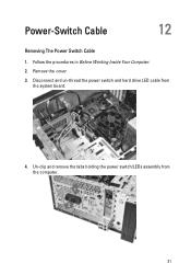
Un-clip and remove the tabs holding the power switch/LEDs assembly from the system board. 4. Remove the cover. 3. Disconnect and un-thread the power switch and hard drive LED cable from the computer. 31 Follow the procedures in Before Working Inside Your Computer. 2. Power-Switch Cable 12 Removing The Power Switch Cable 1.
Un-clip and remove the tabs holding the power switch/LEDs assembly from the system board. 4. Remove the cover. 3. Disconnect and un-thread the power switch and hard drive LED cable from the computer. 31 Follow the procedures in Before Working Inside Your Computer. 2. Power-Switch Cable 12 Removing The Power Switch Cable 1.

Owner's Manual (Mini Tower)
Page 32
Installing The Power Switch Cable 1. Push the power switch/LEDs assembly into the computer till it snaps into place. 2. Follow the procedures in After Working Inside Your Computer. 32 Connect the power switch and hard drive LED cable to the system board. 3. Replace the cover. 4.
Installing The Power Switch Cable 1. Push the power switch/LEDs assembly into the computer till it snaps into place. 2. Follow the procedures in After Working Inside Your Computer. 32 Connect the power switch and hard drive LED cable to the system board. 3. Replace the cover. 4.

Owner's Manual (Mini Tower)
Page 62
...list with the up and make changes to display. - As Enter> to make changes to the Dell option's current and Diagnostics. NOTE: Not all settings listed in Dell installed hardware, power you can view information Diagnostics. Appears on the right side of Setup window. the left side of...Action < F2 > Displays information on any selected item in the System Setup. < Esc > Exit from current view or switch the current view to the Dell Diagnostics page in theDell information about your down -arrow keys. Press Options Field displays the to return to your computer and ...
...list with the up and make changes to display. - As Enter> to make changes to the Dell option's current and Diagnostics. NOTE: Not all settings listed in Dell installed hardware, power you can view information Diagnostics. Appears on the right side of Setup window. the left side of...Action < F2 > Displays information on any selected item in the System Setup. < Esc > Exit from current view or switch the current view to the Dell Diagnostics page in theDell information about your down -arrow keys. Press Options Field displays the to return to your computer and ...

Owner's Manual (Slim Tower)
Page 4
Installing The Hard Drive 23 8 Fan...25 Removing The Fan...25 Installing The Fan...26 9 Power Supply 27 Removing The Power Supply 27 Installing The Power Supply 29 10 Power Switch 31 Removing The Power Switch 31 Installing The Power Switch 32 11 Input/Output Panel 33 Removing The I/O Panel 33 Installing The I/O Panel 36 12 Processor 37 Removing The...
Installing The Hard Drive 23 8 Fan...25 Removing The Fan...25 Installing The Fan...26 9 Power Supply 27 Removing The Power Supply 27 Installing The Power Supply 29 10 Power Switch 31 Removing The Power Switch 31 Installing The Power Switch 32 11 Input/Output Panel 33 Removing The I/O Panel 33 Installing The I/O Panel 36 12 Processor 37 Removing The...

Owner's Manual (Slim Tower)
Page 31
Disconnect the power-switch cable from the slot. 31 Remove the hard drive LED button by pressing on the two latches and pulling it out from the slot. 5. Power Switch Removing The Power Switch 1. Follow the procedures in Before Working Inside Your Computer. 2. Remove the cover. 3. Remove the power button by pulling it out from the system board. 10 4.
Disconnect the power-switch cable from the slot. 31 Remove the hard drive LED button by pressing on the two latches and pulling it out from the slot. 5. Power Switch Removing The Power Switch 1. Follow the procedures in Before Working Inside Your Computer. 2. Remove the cover. 3. Remove the power button by pulling it out from the system board. 10 4.

Owner's Manual (Slim Tower)
Page 32
Replace the cover. 6. Installing The Power Switch 1. Place the hard drive LED button into the slot by pulling it in into place. 4. Insert the power switch and hard drive LED cable through the front of the computer. 2. Follow the procedures in till it snaps into it in After Working Inside Your Computer. 32 6. Connect the power-switch cable to the system board. 5. Slide the power switch and hard drive LED cable out through the front of the computer. Push the power button into it's slot and press it 's slot 3.
Replace the cover. 6. Installing The Power Switch 1. Place the hard drive LED button into the slot by pulling it in into place. 4. Insert the power switch and hard drive LED cable through the front of the computer. 2. Follow the procedures in till it snaps into it in After Working Inside Your Computer. 32 6. Connect the power-switch cable to the system board. 5. Slide the power switch and hard drive LED cable out through the front of the computer. Push the power button into it's slot and press it 's slot 3.
Setup and Features Information Tech Sheet
Page 2
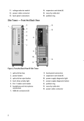
... diagnostic button 12. hard-drive activity light 5. 8-in-1 media-card reader 6. USB 2.0 connectors (2) 8. power cable connector 2 power cable connector 13. back panel connectors 9. padlock ring Figure 2. optical drive eject button 4. voltage selector switch 12. back panel connectors Slim Tower - expansion card slots (4) 15. security cable slot 16. 11. security cable slot 14. expansion...
... diagnostic button 12. hard-drive activity light 5. 8-in-1 media-card reader 6. USB 2.0 connectors (2) 8. power cable connector 2 power cable connector 13. back panel connectors 9. padlock ring Figure 2. optical drive eject button 4. voltage selector switch 12. back panel connectors Slim Tower - expansion card slots (4) 15. security cable slot 16. 11. security cable slot 14. expansion...


