Dell Vostro 2421/2521 Setup And Features Information
Page 1
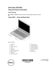
Dell Vostro 2421/2521 Setup And Features Information About Warnings WARNING: A WARNING indicates a potential for property damage, personal injury, or death. touchpad buttons (2) 10. hard-disk activity light 14. microphone 2. wireless status light 12. keyboard 16. optical drive eject button 7. power status light 15. Front and Back View Figure 1. Front View 1. camera status light 4. optical drive 6. USB 2.0 connector 8. power button Regulatory Model: P37G, P27F Regulatory Type: P37G001, P27F001 2012 - 12 battery status light 13. camera 3. SD card reader 11. ...
Dell Vostro 2421/2521 Setup And Features Information About Warnings WARNING: A WARNING indicates a potential for property damage, personal injury, or death. touchpad buttons (2) 10. hard-disk activity light 14. microphone 2. wireless status light 12. keyboard 16. optical drive eject button 7. power status light 15. Front and Back View Figure 1. Front View 1. camera status light 4. optical drive 6. USB 2.0 connector 8. power button Regulatory Model: P37G, P27F Regulatory Type: P37G001, P27F001 2012 - 12 battery status light 13. camera 3. SD card reader 11. ...
Dell Vostro 2421/2521 Setup And Features Information
Page 3
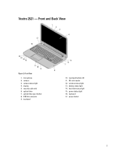
microphone 2. wireless status light 13. battery status light 14. power button 3 USB 2.0 connector 9. Front View 1. optical drive eject button 8. SD card reader 12. keyboard 17. camera status light 4. touchpad buttons (2) 11. power status light 16. Vostro 2521 - camera 3. hard-disk status light 15. Front and Back View Figure 3. optical drive 7. display 5. touchpad 10. security cable slot 6.
microphone 2. wireless status light 13. battery status light 14. power button 3 USB 2.0 connector 9. Front View 1. optical drive eject button 8. SD card reader 12. keyboard 17. camera status light 4. touchpad buttons (2) 11. power status light 16. Vostro 2521 - camera 3. hard-disk status light 15. Front and Back View Figure 3. optical drive 7. display 5. touchpad 10. security cable slot 6.
Dell Vostro 2521 Owner's Manual
Page 3
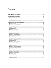
... Card...9 Removing the Battery...9 Installing the Battery...10 Removing the Access Panel...10 Installing the Access Panel...10 Removing the Memory Module...11 Installing the Memory Module...11 Removing the Hard-Drive Assembly...11 Installing the Hard-Drive Assembly...13 Removing the Optical-Drive Assembly...13 Installing the Optical-Drive Assembly...14 Removing the Keyboard...14 Installing the Keyboard...15 Removing the Wireless Mini-Card...16 Installing the Wireless Mini-Card...16 Removing the Palmrest...16 Installing the Palmrest...18 Removing the Input/Output (I/O) Board...18 Installing the...
... Card...9 Removing the Battery...9 Installing the Battery...10 Removing the Access Panel...10 Installing the Access Panel...10 Removing the Memory Module...11 Installing the Memory Module...11 Removing the Hard-Drive Assembly...11 Installing the Hard-Drive Assembly...13 Removing the Optical-Drive Assembly...13 Installing the Optical-Drive Assembly...14 Removing the Keyboard...14 Installing the Keyboard...15 Removing the Wireless Mini-Card...16 Installing the Wireless Mini-Card...16 Removing the Palmrest...16 Installing the Palmrest...18 Removing the Input/Output (I/O) Board...18 Installing the...
Dell Vostro 2521 Owner's Manual
Page 4
... Removing the Display Hinges...28 Installing the Display Hinges...28 Removing the Display Panel...29 Installing the Display Panel...30 Removing the Camera Module...30 Installing the Camera Module...31 3 System Setup...33 Boot Sequence...33 Navigation Keys...33 System Setup Options...34 Updating the BIOS ...37 System and Setup Password...37 Assigning a System Password and Setup Password 38 Deleting or Changing an Existing System and/or Setup Password 38 4 Diagnostics...41 Enhanced Pre-Boot System Assessment (ePSA) Diagnostics 41 Battery Status Lights...41 5 Troubleshooting...
... Removing the Display Hinges...28 Installing the Display Hinges...28 Removing the Display Panel...29 Installing the Display Panel...30 Removing the Camera Module...30 Installing the Camera Module...31 3 System Setup...33 Boot Sequence...33 Navigation Keys...33 System Setup Options...34 Updating the BIOS ...37 System and Setup Password...37 Assigning a System Password and Setup Password 38 Deleting or Changing an Existing System and/or Setup Password 38 4 Diagnostics...41 Enhanced Pre-Boot System Assessment (ePSA) Diagnostics 41 Battery Status Lights...41 5 Troubleshooting...
Dell Vostro 2521 Owner's Manual
Page 5
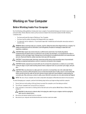
... the cable from the network device. 4. CAUTION: To avoid electrostatic discharge, ground yourself by using a wrist grounding strap or by its pull-tab, not on the cable itself. To avoid damaging your computer, perform the following steps before you connect a cable, ensure that your work surface is connected to servicing that came with locking tabs; Also, before you pull connectors apart, keep...
... the cable from the network device. 4. CAUTION: To avoid electrostatic discharge, ground yourself by using a wrist grounding strap or by its pull-tab, not on the cable itself. To avoid damaging your computer, perform the following steps before you connect a cable, ensure that your work surface is connected to servicing that came with locking tabs; Also, before you pull connectors apart, keep...
Dell Vostro 2521 Owner's Manual
Page 6
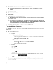
... the operating system: - Click Start . 2. Click Shut Down. or 1. NOTE: To avoid damaging the system board, you must remove the main battery before opening the Charms menu and select Settings. Remove the main battery. 8. CAUTION: To guard against electrical shock, always unplug your computer. 1. Remove any installed ExpressCards or Smart Cards from the right edge of the screen and click Settings. In Windows 8: * Using a touch-enabled device: a. Press the power button to...
... the operating system: - Click Start . 2. Click Shut Down. or 1. NOTE: To avoid damaging the system board, you must remove the main battery before opening the Charms menu and select Settings. Remove the main battery. 8. CAUTION: To guard against electrical shock, always unplug your computer. 1. Remove any installed ExpressCards or Smart Cards from the right edge of the screen and click Settings. In Windows 8: * Using a touch-enabled device: a. Press the power button to...
Dell Vostro 2521 Owner's Manual
Page 7
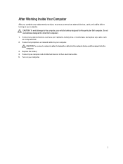
... network cables to their electrical outlets. 5. CAUTION: To connect a network cable, first plug the cable into the network device and then plug it into the computer. 3. Connect your computer and all attached devices to your computer. After Working Inside Your Computer After you complete any replacement procedure, ensure you connect any external devices, cards, and cables before turning on your computer. Do not use only the battery designed for other Dell...
... network cables to their electrical outlets. 5. CAUTION: To connect a network cable, first plug the cable into the network device and then plug it into the computer. 3. Connect your computer and all attached devices to your computer. After Working Inside Your Computer After you complete any replacement procedure, ensure you connect any external devices, cards, and cables before turning on your computer. Do not use only the battery designed for other Dell...
Dell Vostro 2521 Owner's Manual
Page 13
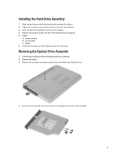
... in the computer. 4. Remove the battery. 3. Replace the screws to secure the hard-drive assembly to the optical-drive assembly. 13 Remove the screw that secure the optical-drive bracket to the computer. 5. Install: a) memory module b) access panel c) battery 6. Slide the hard-drive assembly in its slot in Before Working Inside Your Computer. 2. Installing the Hard-Drive Assembly 1. Removing the Optical-Drive Assembly 1. Remove the screws that secures the optical drive and slide it into...
... in the computer. 4. Remove the battery. 3. Replace the screws to secure the hard-drive assembly to the optical-drive assembly. 13 Remove the screw that secure the optical-drive bracket to the computer. 5. Install: a) memory module b) access panel c) battery 6. Slide the hard-drive assembly in its slot in Before Working Inside Your Computer. 2. Installing the Hard-Drive Assembly 1. Removing the Optical-Drive Assembly 1. Remove the screws that secures the optical drive and slide it into...
Dell Vostro 2521 Owner's Manual
Page 23
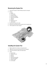
... to secure the system fan to the system board. 5. Install: a) system board b) wireless mini-card c) plamrest d) keyboard e) optical-drive assembly f) hard-drive assembly g) memory module h) access panel 23 Remove: a) battery b) access panel c) memory module d) hard-drive assembly e) optical-drive assembly f) keyboard g) palmrest h) wireless mini-card i) system board 3. Remove the screw that secures the system fan to the computer. 3. Installing the System Fan 1. Connect the system-fan cable to the system board. 4. Align the system fan in Before Working Inside Your Computer. 2. Lift...
... to secure the system fan to the system board. 5. Install: a) system board b) wireless mini-card c) plamrest d) keyboard e) optical-drive assembly f) hard-drive assembly g) memory module h) access panel 23 Remove: a) battery b) access panel c) memory module d) hard-drive assembly e) optical-drive assembly f) keyboard g) palmrest h) wireless mini-card i) system board 3. Remove the screw that secures the system fan to the computer. 3. Installing the System Fan 1. Connect the system-fan cable to the system board. 4. Align the system fan in Before Working Inside Your Computer. 2. Lift...
Dell Vostro 2521 Owner's Manual
Page 25
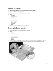
... the LVDS and camera cables to the computer. 3. Follow the procedures in After Working Inside Your Computer. Disconnect the wireless-mini card antennae from connector on the system board. 25 Replace the LED silicon tubes to the system board and disconnect them from the connector on the system board. Install: a) system board b) wireless mini-card c) palmrest d) keyboard e) optical-drive assembly f) hard-drive assembly g) memory module h) access panel i) battery 5. Removing the Display Assembly 1. Installing the Speakers 1. Place...
... the LVDS and camera cables to the computer. 3. Follow the procedures in After Working Inside Your Computer. Disconnect the wireless-mini card antennae from connector on the system board. 25 Replace the LED silicon tubes to the system board and disconnect them from the connector on the system board. Install: a) system board b) wireless mini-card c) palmrest d) keyboard e) optical-drive assembly f) hard-drive assembly g) memory module h) access panel i) battery 5. Removing the Display Assembly 1. Installing the Speakers 1. Place...

Dell Vostro 2521 Owner's Manual
Page 26
... the wireless mini-card. 4. Remove: a) battery b) access panel 26 Installing the Display Assembly 1. Tighten the screws to secure the LVDS and camera assembly to the computer. 6. Install: a) palmrest b) keyboard c) optical-drive assembly d) hard-drive assembly e) memory module f) access panel g) battery 7. Follow the procedures in Before Working Inside Your Computer. 2. Removing the Display Bezel 1. Connect the display and power port cables to the computer and lift the display assembly off the computer. Move the LVDS and camera cable aside and remove the...
... the wireless mini-card. 4. Remove: a) battery b) access panel 26 Installing the Display Assembly 1. Tighten the screws to secure the LVDS and camera assembly to the computer. 6. Install: a) palmrest b) keyboard c) optical-drive assembly d) hard-drive assembly e) memory module f) access panel g) battery 7. Follow the procedures in Before Working Inside Your Computer. 2. Removing the Display Bezel 1. Connect the display and power port cables to the computer and lift the display assembly off the computer. Move the LVDS and camera cable aside and remove the...
Dell Vostro 2521 Owner's Manual
Page 30
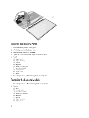
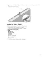
Install: a) display bezel b) display assembly c) palmrest d) keyboard e) optical-drive assembly f) hard-drive assembly g) memory module h) access panel i) battery 6. Connect the display cable to the computer. 5. Installing the Display Panel 1. Tighten the screws to secure the display panel to display panel. 2. Removing the Camera Module 1. Remove: a) battery b) memory module c) hard-drive assembly d) optical-drive assembly e) keyboard f) palmrest g) display assembly h) display bezel 30 Affix the tape to secure the display cable. 3. Follow the procedures in After Working ...
Install: a) display bezel b) display assembly c) palmrest d) keyboard e) optical-drive assembly f) hard-drive assembly g) memory module h) access panel i) battery 6. Connect the display cable to the computer. 5. Installing the Display Panel 1. Tighten the screws to secure the display panel to display panel. 2. Removing the Camera Module 1. Remove: a) battery b) memory module c) hard-drive assembly d) optical-drive assembly e) keyboard f) palmrest g) display assembly h) display bezel 30 Affix the tape to secure the display cable. 3. Follow the procedures in After Working ...
Dell Vostro 2521 Owner's Manual
Page 31
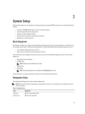
... secure the camera module to the camera module. 5. Affix the tape to the computer. 4. Install: a) display bezel b) display assembly c) palmrest d) keyboard e) optical-drive assembly f) hard-drive assembly g) memory module h) battery 6. Remove the screw, peel the tape and disconnect the camera cable from the connector and remove the camera module from the display assembly. Align the camera module in After Working Inside Your Computer. 31 Follow the instructions in its position on the camera module. 2. Installing the Camera Module 1. 3. Connect the camera cable to...
... secure the camera module to the camera module. 5. Affix the tape to the computer. 4. Install: a) display bezel b) display assembly c) palmrest d) keyboard e) optical-drive assembly f) hard-drive assembly g) memory module h) battery 6. Remove the screw, peel the tape and disconnect the camera cable from the connector and remove the camera module from the display assembly. Align the camera module in After Working Inside Your Computer. 31 Follow the instructions in its position on the camera module. 2. Installing the Camera Module 1. 3. Connect the camera cable to...
Dell Vostro 2521 Owner's Manual
Page 33
... system hardware configuration • Enable or disable integrated devices • Set performance and power management thresholds • Manage your computer hardware and specify BIOS‐level options. Table 1. From the System Setup, you can : • Access System Setup by pressing key • Bring up the one-time boot menu by pressing key The one-time boot menu displays the devices that you make are : • Removable Drive (if available) • STXXXX Drive NOTE: XXX denotes the SATA drive number...
... system hardware configuration • Enable or disable integrated devices • Set performance and power management thresholds • Manage your computer hardware and specify BIOS‐level options. Table 1. From the System Setup, you can : • Access System Setup by pressing key • Bring up the one-time boot menu by pressing key The one-time boot menu displays the devices that you make are : • Removable Drive (if available) • STXXXX Drive NOTE: XXX denotes the SATA drive number...
Dell Vostro 2521 Owner's Manual
Page 36
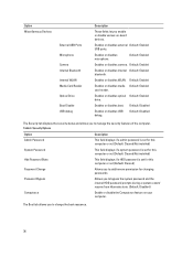
... Password This field displays if a system password is set for this computer or not (Default: Cleared/Not installed) Hdd Password State This field displays if a HDD password is set for this computer or not (Default: Cleared) Password Change Allows you to add/remove permission for changing passwords. Option Miscellaneous Devices External USB Ports Microphone Camera Internal Bluetooth Internal WLAN Media Card Reader Optical Drive Boot Disable USB debug Description These fields let you enable or disable various on your computer. Enables or disables external Default: Enabled USB ports...
... Password This field displays if a system password is set for this computer or not (Default: Cleared/Not installed) Hdd Password State This field displays if a HDD password is set for this computer or not (Default: Cleared) Password Change Allows you to add/remove permission for changing passwords. Option Miscellaneous Devices External USB Ports Microphone Camera Internal Bluetooth Internal WLAN Media Card Reader Optical Drive Boot Disable USB debug Description These fields let you enable or disable various on your computer. Enables or disables external Default: Enabled USB ports...
Dell Vostro 2521 Owner's Manual
Page 37
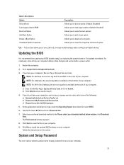
... , discard, and load default settings before exiting from a list of your BIOS (system setup), on replacing the system board or if an update is recommended to delete a boot option. Go to step 5. 4. On the application and drivers screen, under the Operating System drop-down list, select BIOS. 6. The File Download window appears. 8. Follow the instructions on the front of your computer's service tag or express service code, select one of the...
... , discard, and load default settings before exiting from a list of your BIOS (system setup), on replacing the system board or if an update is recommended to delete a boot option. Go to step 5. 4. On the application and drivers screen, under the Operating System drop-down list, select BIOS. 6. The File Download window appears. 8. Follow the instructions on the front of your computer's service tag or express service code, select one of the...
Dell Vostro 2521 Owner's Manual
Page 38
... is disabled, the existing System Password and Setup Password is Unlocked. 3. To enter a system setup, press immediately after a power-on your system password and press or . Only the following guidelines to your computer. Use the following special characters are not allowed. - In the System BIOS or System Setup screen, select System Security and press . Type the setup password that Password Status is deleted and you to the BIOS settings...
... is disabled, the existing System Password and Setup Password is Unlocked. 3. To enter a system setup, press immediately after a power-on your system password and press or . Only the following guidelines to your computer. Use the following special characters are not allowed. - In the System BIOS or System Setup screen, select System Security and press . Type the setup password that Password Status is deleted and you to the BIOS settings...
Dell Vostro 2521 Owner's Manual
Page 41
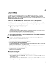
... failed device(s) • View status messages that inform you if tests are unable to fix the problem yourself, service and support personnel can use the diagnostics results to stop the diagnostic test. 5. If there are any issues, error codes are performed. 1. Note the error code and contact Dell. On the boot menu screen, select the Diagnostics option. Temporary battery failure with steady white light - Enhanced Pre-Boot System...
... failed device(s) • View status messages that inform you if tests are unable to fix the problem yourself, service and support personnel can use the diagnostics results to stop the diagnostic test. 5. If there are any issues, error codes are performed. 1. Note the error code and contact Dell. On the boot menu screen, select the Diagnostics option. Temporary battery failure with steady white light - Enhanced Pre-Boot System...
Dell Vostro 2521 Owner's Manual
Page 43
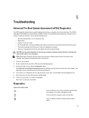
... tests are displayed. Power-on the computer and blinks when the computer is launched by the BIOS internally. As the computer boots, press the key as system diagnostics) performs a complete check of problems encountered during testing CAUTION: Use the system diagnostics to indicate battery charge status. 43 Diagnostics Table 6. Using this program with the BIOS and is in the computer. 5 Troubleshooting Enhanced Pre-Boot System Assessment...
... tests are displayed. Power-on the computer and blinks when the computer is launched by the BIOS internally. As the computer boots, press the key as system diagnostics) performs a complete check of problems encountered during testing CAUTION: Use the system diagnostics to indicate battery charge status. 43 Diagnostics Table 6. Using this program with the BIOS and is in the computer. 5 Troubleshooting Enhanced Pre-Boot System Assessment...
Dell Vostro 2521 Owner's Manual
Page 44
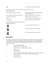
... each set of beeps is enabled. Battery Status Lights Alternately blinking amber light and blue light Alternately blinking amber light with AC adapter present. The lights located above the keyboard indicate the following: Table 8. If the computer is attached to an electrical outlet, the battery light operates as follows: Table 7. Code 1 Cause and Troubleshooting Steps BIOS ROM checksum in charge mode with steady blue light Constantly blinking amber light An unauthenticated or unsupported non-Dell AC adapter is connected...
... each set of beeps is enabled. Battery Status Lights Alternately blinking amber light and blue light Alternately blinking amber light with AC adapter present. The lights located above the keyboard indicate the following: Table 8. If the computer is attached to an electrical outlet, the battery light operates as follows: Table 7. Code 1 Cause and Troubleshooting Steps BIOS ROM checksum in charge mode with steady blue light Constantly blinking amber light An unauthenticated or unsupported non-Dell AC adapter is connected...


