Vostro 220 Power Supply - Dell Slim Desktop Computer
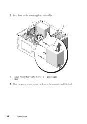
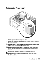
Vostro 220 Power Supply
Related Manual Pages


Related Videos

How To: Upgrade PSU and Video Card Dell Vostro 200 MINI-TOWER Desktop PC
Duration: 1:33:34
Total Views: 8,524
Duration: 1:33:34
Total Views: 8,524
Similar Questions

How Do You Know The Power Supply Is Dying?
My desktop won't wake up when in sleep mode. Is it possible the power supply is going? What does the...
My desktop won't wake up when in sleep mode. Is it possible the power supply is going? What does the...
(Posted by edgewater20 9 years ago)

How To Remove Power Supply From Dell Inspiron 660s
I can't find a way to take out the old power supply in my Inspiron 660s. It's loose but there I no r...
I can't find a way to take out the old power supply in my Inspiron 660s. It's loose but there I no r...
(Posted by sfishesfish 10 years ago)

Power Supply Connection Cables
I removed the power supply and misplaced some of my post it notes. I can't figure out for sure where...
I removed the power supply and misplaced some of my post it notes. I can't figure out for sure where...
(Posted by Slr29 11 years ago)