Dell™ Technology Guide
Page 11
... 140 Uninterruptible Power Supply (UPS 141 Laptop Computer Batteries 141 Using Your Laptop Computer for the First Time 142 Preserving the Life of a Battery 142 Replacing a Battery 143 Checking the Battery Charge 143 Conserving Battery Power 145 Charging the Battery 145 Storing a Battery 146 US Department of Transportation (DOT) Notebook Battery Restrictions 146 Dell™ ControlPoint Power Manager...
... 140 Uninterruptible Power Supply (UPS 141 Laptop Computer Batteries 141 Using Your Laptop Computer for the First Time 142 Preserving the Life of a Battery 142 Replacing a Battery 143 Checking the Battery Charge 143 Conserving Battery Power 145 Charging the Battery 145 Storing a Battery 146 US Department of Transportation (DOT) Notebook Battery Restrictions 146 Dell™ ControlPoint Power Manager...
Dell™ Technology Guide
Page 279
... may be defective. WARNING: THE BATTERY ATTACHED CANNOT POWER THE SYSTEM. PRESS F1 TO SHUTDOWN THE S YS T E M . WA R N I N G : T H E T P M C O U L D N O T B E I N I T I A L I S R E M O V E D . - IT IS ADVISABLE TO IMMEDIATELY BACK UP YOUR DATA AND REPLACE YOUR HARD DRIVE BY CALLING YOUR SUPPORT DESK OR ...DELL'S DISK MONITORING SYSTEM HAS DETECTED THAT DRIVE [0/1] ON THE [PRIMARY/SECONDARY] EIDE CONTROLLER IS OPERATING OUTSIDE OF NORMAL SPECIFICATIONS. YOUR POWER ADAPTER DOES NOT SUPPLY ENOUGH POWER TO RUN THE ATTACHED DOCKING STATION. Connect the correct AC adapter to the computer...
... may be defective. WARNING: THE BATTERY ATTACHED CANNOT POWER THE SYSTEM. PRESS F1 TO SHUTDOWN THE S YS T E M . WA R N I N G : T H E T P M C O U L D N O T B E I N I T I A L I S R E M O V E D . - IT IS ADVISABLE TO IMMEDIATELY BACK UP YOUR DATA AND REPLACE YOUR HARD DRIVE BY CALLING YOUR SUPPORT DESK OR ...DELL'S DISK MONITORING SYSTEM HAS DETECTED THAT DRIVE [0/1] ON THE [PRIMARY/SECONDARY] EIDE CONTROLLER IS OPERATING OUTSIDE OF NORMAL SPECIFICATIONS. YOUR POWER ADAPTER DOES NOT SUPPLY ENOUGH POWER TO RUN THE ATTACHED DOCKING STATION. Connect the correct AC adapter to the computer...
Service Manual
Page 6
8 I/O Panel 89 Removing the I/O Panel 89 Replacing the I/O Panel 91 9 Fan 93 Removing the Chassis Fan 93 Replacing the Chassis Fan 97 10 Processor Heat Sink/Fan Assembly . . . 99 Removing the Processor Heat Sink/Fan Assembly . . . 99 Replacing the Processor Heat Sink/Fan Assembly 101 11 Memory Module(s 103 Removing Memory Modules 103 Replacing or Adding a Memory Module 104 12 Power Supply 107 Removing the Power Supply 107 Replacing the Power Supply 109 DC Power Supply Connectors 110 DC Power Supply Connector Pin Assignments . . . . 112 6 Contents
8 I/O Panel 89 Removing the I/O Panel 89 Replacing the I/O Panel 91 9 Fan 93 Removing the Chassis Fan 93 Replacing the Chassis Fan 97 10 Processor Heat Sink/Fan Assembly . . . 99 Removing the Processor Heat Sink/Fan Assembly . . . 99 Replacing the Processor Heat Sink/Fan Assembly 101 11 Memory Module(s 103 Removing Memory Modules 103 Replacing or Adding a Memory Module 104 12 Power Supply 107 Removing the Power Supply 107 Replacing the Power Supply 109 DC Power Supply Connectors 110 DC Power Supply Connector Pin Assignments . . . . 112 6 Contents
Service Manual
Page 107
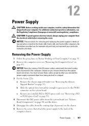
... present) in "Before Working on Your Computer" on page 35. 2 Remove the computer cover (see the Regulatory Compliance Homepage at www.dell.com/regulatory_compliance. You must reroute these cables properly when you remove them from the system board and drives. NOTICE: The procedure for removing and replacing the power supply is identical (except where noted) for...
... present) in "Before Working on Your Computer" on page 35. 2 Remove the computer cover (see the Regulatory Compliance Homepage at www.dell.com/regulatory_compliance. You must reroute these cables properly when you remove them from the system board and drives. NOTICE: The procedure for removing and replacing the power supply is identical (except where noted) for...
Service Manual
Page 109
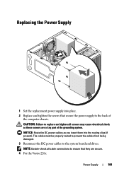
... computer chassis. The cables must be properly routed to prevent the cables from being damaged. 3 Reconnect the DC power cables to replace and tighten all cable connections to ensure that secure the power supply to the back of the grounding system. NOTICE: Route the DC power cables as these screws are secure. 4 For the Vostro 220s: Power Supply 109 Replacing the Power Supply...
... computer chassis. The cables must be properly routed to prevent the cables from being damaged. 3 Reconnect the DC power cables to replace and tighten all cable connections to ensure that secure the power supply to the back of the grounding system. NOTICE: Route the DC power cables as these screws are secure. 4 For the Vostro 220s: Power Supply 109 Replacing the Power Supply...
Service Manual
Page 110
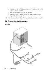
a Reinstall any PCI or PCI Express cards (see "Replacing the Chassis Support Bracket" on page 57). 5 Follow the procedure in "After Working on Your Computer" on page 60). DC Power Supply Connectors Vostro 420 P10 P2 P3 P9 P8 P4 P7 P5 P1 P6 110 Power Supply b Slide the optical drive back into the drive bay. c Replace the chassis support bracket (see "Installing a PCI or PCI Express Card" on page 45.
a Reinstall any PCI or PCI Express cards (see "Replacing the Chassis Support Bracket" on page 57). 5 Follow the procedure in "After Working on Your Computer" on page 60). DC Power Supply Connectors Vostro 420 P10 P2 P3 P9 P8 P4 P7 P5 P1 P6 110 Power Supply b Slide the optical drive back into the drive bay. c Replace the chassis support bracket (see "Installing a PCI or PCI Express Card" on page 45.
Service Manual
Page 123
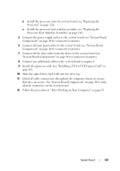
a Install the processor heat sink/fan assembly (see "Replacing the Processor Heat Sink/Fan Assembly" on page 101). 5 Connect the power supply cables to the system board (see "System Board Components" on page 40 for connector locations). 6 Connect all front panel cables to the system ... any additional cables to the system board as required. 9 Install all cable connections throughout the computer chassis to help identify connectors on the system board. 12 Follow the procedure in "After Working on Your Computer" on page 45. See "System Board Components" on page 40 to ensure that they are...
a Install the processor heat sink/fan assembly (see "Replacing the Processor Heat Sink/Fan Assembly" on page 101). 5 Connect the power supply cables to the system board (see "System Board Components" on page 40 for connector locations). 6 Connect all front panel cables to the system ... any additional cables to the system board as required. 9 Install all cable connections throughout the computer chassis to help identify connectors on the system board. 12 Follow the procedure in "After Working on Your Computer" on page 45. See "System Board Components" on page 40 to ensure that they are...


