
Setup and Quick Reference Guide
Page 7
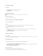
About Your Computer Front View Dell™ Vostro™ 1310 13 12 1 display 3 device status lights 1 2 3 4 5 6 9 A 7 8 9 11 10 2 power button 4 keyboard status lights About Your Computer 7
About Your Computer Front View Dell™ Vostro™ 1310 13 12 1 display 3 device status lights 1 2 3 4 5 6 9 A 7 8 9 11 10 2 power button 4 keyboard status lights About Your Computer 7
Setup and Quick Reference Guide
Page 8
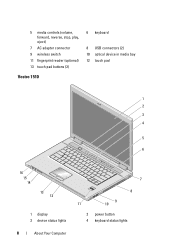
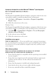
5 media controls (volume, forward, reverse, stop, play, eject) 7 AC adapter connector 9 wireless switch 11 fingerprint reader (optional) 13 touch pad buttons (2) Vostro 1510 6 keyboard 8 USB connectors (2) 10 optical device in media bay 12 touch pad 1 2 3 4 5 6 9 A 16 15 14 13 12 1 display 3 device status lights 8 About Your Computer 7 8 9 11 10 2 power button 4 keyboard status lights
5 media controls (volume, forward, reverse, stop, play, eject) 7 AC adapter connector 9 wireless switch 11 fingerprint reader (optional) 13 touch pad buttons (2) Vostro 1510 6 keyboard 8 USB connectors (2) 10 optical device in media bay 12 touch pad 1 2 3 4 5 6 9 A 16 15 14 13 12 1 display 3 device status lights 8 About Your Computer 7 8 9 11 10 2 power button 4 keyboard status lights
Setup and Quick Reference Guide
Page 9
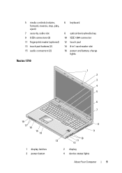
5 media controls (volume, forward, reverse, stop, play, eject) 7 security cable slot 9 USB connectors (2) 11 fingerprint reader (optional) 13 touch pad buttons (2) 15 audio connectors (2) Vostro 1710 6 keyboard 8 optical device/media bay 10 IEEE 1394 connector 12 touch pad 14 8-in1 card reader slot 16 power and battery charge lights 1 2 3 4 5 6 9 7 A 18 17 16 15 14 1 display latches 3 power button 8 9 10 13 11 12 2 display 4 device status lights About Your Computer 9
5 media controls (volume, forward, reverse, stop, play, eject) 7 security cable slot 9 USB connectors (2) 11 fingerprint reader (optional) 13 touch pad buttons (2) 15 audio connectors (2) Vostro 1710 6 keyboard 8 optical device/media bay 10 IEEE 1394 connector 12 touch pad 14 8-in1 card reader slot 16 power and battery charge lights 1 2 3 4 5 6 9 7 A 18 17 16 15 14 1 display latches 3 power button 8 9 10 13 11 12 2 display 4 device status lights About Your Computer 9
Setup and Quick Reference Guide
Page 10
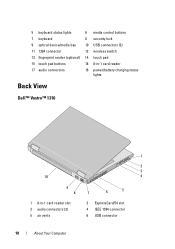
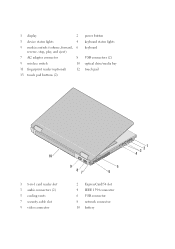
5 keyboard status lights 6 media control buttons 7 keyboard 8 security lock 9 optical device/media bay 10 USB connectors (2) 11 1394 connector 12 wireless switch 13 fingerprint reader (optional) 14 touch pad 15 touch pad buttons 16 8-in-1 card reader 17 audio connectors 18 power/battery charging status lights Back View Dell™ Vostro™ 1310 1 2 3 10 4 9 8 7 6 5 1 8-in-1 card reader slot 3 audio connectors (2) 5 air vents 2 ExpressCard/54 slot 4 IEEE 1394 connector 6 USB connector 10 About Your Computer
5 keyboard status lights 6 media control buttons 7 keyboard 8 security lock 9 optical device/media bay 10 USB connectors (2) 11 1394 connector 12 wireless switch 13 fingerprint reader (optional) 14 touch pad 15 touch pad buttons 16 8-in-1 card reader 17 audio connectors 18 power/battery charging status lights Back View Dell™ Vostro™ 1310 1 2 3 10 4 9 8 7 6 5 1 8-in-1 card reader slot 3 audio connectors (2) 5 air vents 2 ExpressCard/54 slot 4 IEEE 1394 connector 6 USB connector 10 About Your Computer
Setup and Quick Reference Guide
Page 16
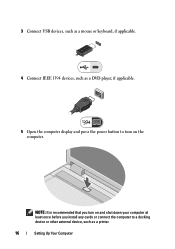
3 Connect USB devices, such as a mouse or keyboard, if applicable. 4 Connect IEEE 1394 devices, such as a printer. 16 Setting Up Your Computer NOTE: It is recommended that you turn on and shut down your computer at least once before you install any cards or connect the computer to a docking device or other external device, such as a DVD player, if applicable. 5 Open the computer display and press the power button to turn on the computer.
3 Connect USB devices, such as a mouse or keyboard, if applicable. 4 Connect IEEE 1394 devices, such as a printer. 16 Setting Up Your Computer NOTE: It is recommended that you turn on and shut down your computer at least once before you install any cards or connect the computer to a docking device or other external device, such as a DVD player, if applicable. 5 Open the computer display and press the power button to turn on the computer.
Setup and Quick Reference Guide
Page 35
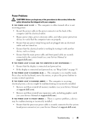
...: Before you that the display is connected and powered on. • If the power light is blinking blue, the computer is not responding, ensure that the computer encountered a possible motherboard failure. Tools Power Lights The two-color power-button light located on the keyboard, move the mouse,... or press the power button to indicate different states: • If the power light is off, the computer is either turned off or is...
...: Before you that the display is connected and powered on. • If the power light is blinking blue, the computer is not responding, ensure that the computer encountered a possible motherboard failure. Tools Power Lights The two-color power-button light located on the keyboard, move the mouse,... or press the power button to indicate different states: • If the power light is off, the computer is either turned off or is...
Setup and Quick Reference Guide
Page 45
... M B E R - Press a key on the keyboard, move the mouse, or press the power button to the system board (see your Service Manual at support.dell.com). Troubleshooting 45 The computer is a power problem, a device may be malfunctioning or incorrectly installed. • Remove and then reinstall all memory ...modules (see your Service Manual at support.dell.com). • Remove and then reinstall any power strips being used are plugged into an electrical outlet and are securely connected to resume normal operation. I ...
... M B E R - Press a key on the keyboard, move the mouse, or press the power button to the system board (see your Service Manual at support.dell.com). Troubleshooting 45 The computer is a power problem, a device may be malfunctioning or incorrectly installed. • Remove and then reinstall all memory ...modules (see your Service Manual at support.dell.com). • Remove and then reinstall any power strips being used are plugged into an electrical outlet and are securely connected to resume normal operation. I ...
Setup and Quick Reference Guide
Page 47
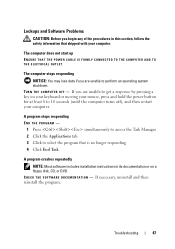
... the computer turns off), and then restart your computer. Troubleshooting 47 The computer does not start up ENSURE THAT THE POWER CABLE IS FIRMLY CONNECTED TO THE COMPUTER AND TO THE ELECTRICAL OUTLET The computer stops responding NOTICE: You may lose data... if you begin any of the procedures in its documentation or on your keyboard or moving your mouse, press and hold the power button for at least 8 to select the program that shipped with your computer. If you are unable to perform an operating system shutdown. C H E C K T H E S O F T W A R E D O C U M E N ...
... the computer turns off), and then restart your computer. Troubleshooting 47 The computer does not start up ENSURE THAT THE POWER CABLE IS FIRMLY CONNECTED TO THE COMPUTER AND TO THE ELECTRICAL OUTLET The computer stops responding NOTICE: You may lose data... if you begin any of the procedures in its documentation or on your keyboard or moving your mouse, press and hold the power button for at least 8 to select the program that shipped with your computer. If you are unable to perform an operating system shutdown. C H E C K T H E S O F T W A R E D O C U M E N ...
Setup and Quick Reference Guide
Page 48
... information. • Ensure that the program is compatible with the operating system installed on your computer. • Ensure that your mouse, press and hold the power button for at least 8 to non-Windows Vista operating system environments. 1 Click Start → Control Panel→ Programs→ Use an older program with this version...
... information. • Ensure that the program is compatible with the operating system installed on your computer. • Ensure that your mouse, press and hold the power button for at least 8 to non-Windows Vista operating system environments. 1 Click Start → Control Panel→ Programs→ Use an older program with this version...
Setup and Features Information Tech Sheet
Page 2
1 display 2 3 device status lights 4 5 media controls (volume, forward, 6 reverse, stop, play, and eject) 7 AC adapter connector 8 9 wireless switch 10 11 fingerprint reader (optional) 12 13 touch pad buttons (2) power button keyboard status lights keyboard USB connectors (2) optical drive/media bay touch pad 10 1 8-in-1 card reader slot 3 audio connectors (2) 5 cooling vents 7 security cable slot 9 video connector 9 87 5 6 2 ExpressCard/54 slot 4 IEEE 1394 connector 6 USB connector 8 network connector 10 battery 3 21 4
1 display 2 3 device status lights 4 5 media controls (volume, forward, 6 reverse, stop, play, and eject) 7 AC adapter connector 8 9 wireless switch 10 11 fingerprint reader (optional) 12 13 touch pad buttons (2) power button keyboard status lights keyboard USB connectors (2) optical drive/media bay touch pad 10 1 8-in-1 card reader slot 3 audio connectors (2) 5 cooling vents 7 security cable slot 9 video connector 9 87 5 6 2 ExpressCard/54 slot 4 IEEE 1394 connector 6 USB connector 8 network connector 10 battery 3 21 4

Setup and Features Information Tech Sheet
Page 3
The chassis color of Vostro 1510 is Black and the chassis color of Vostro 2510 is the color of the chassis. Vostro 1510/2510 NOTE: The difference between Vostro 1510 and Vostro 2510 is Cherry Red. 1 2 3 4 5 6 9 A 16 15 14 13 12 11 9 10 1 display 2 3 device status lights 4 5 media controls (volume, forward, 6 reverse, stop, play, and eject) power button keyboard status lights keyboard 7 8
The chassis color of Vostro 1510 is Black and the chassis color of Vostro 2510 is the color of the chassis. Vostro 1510/2510 NOTE: The difference between Vostro 1510 and Vostro 2510 is Cherry Red. 1 2 3 4 5 6 9 A 16 15 14 13 12 11 9 10 1 display 2 3 device status lights 4 5 media controls (volume, forward, 6 reverse, stop, play, and eject) power button keyboard status lights keyboard 7 8
Setup and Features Information Tech Sheet
Page 5
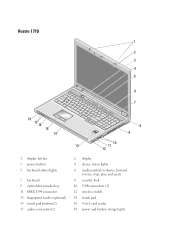
Vostro 1710 1 2 3 4 5 6 9 7 A 18 17 16 15 14 8 9 10 13 11 12 1 display latches 3 power button 5 keyboard status lights 7 keyboard 9 optical drive/media bay 11 IEEE 1394 connector 13 fingerprint reader (optional) 15 touch pad buttons(2) 17 audio connectors(2) 2 display 4 device status lights 6 media controls (volume, forward, reverse, stop, play, and eject) 8 security lock 10 USB connectors (2) 12 wireless switch 14 touch pad 16 8-in-1 card reader 18 power and battery charge lights
Vostro 1710 1 2 3 4 5 6 9 7 A 18 17 16 15 14 8 9 10 13 11 12 1 display latches 3 power button 5 keyboard status lights 7 keyboard 9 optical drive/media bay 11 IEEE 1394 connector 13 fingerprint reader (optional) 15 touch pad buttons(2) 17 audio connectors(2) 2 display 4 device status lights 6 media controls (volume, forward, reverse, stop, play, and eject) 8 security lock 10 USB connectors (2) 12 wireless switch 14 touch pad 16 8-in-1 card reader 18 power and battery charge lights

Setup and Features Information Tech Sheet
Page 7
... network cable. 3 Connect USB devices, such as a mouse or keyboard. 4 Connect IEEE 1394 devices, such as a DVD player. 5 Open the computer display and press the power button to avoid damaging the cable. NOTE: Some devices may not be included if you did not order them. 1 Connect the AC adapter to the AC...
... network cable. 3 Connect USB devices, such as a mouse or keyboard. 4 Connect IEEE 1394 devices, such as a DVD player. 5 Open the computer display and press the power button to avoid damaging the cable. NOTE: Some devices may not be included if you did not order them. 1 Connect the AC adapter to the AC...

Service Manual
Page 1
... this document to avoid the problem. September 2009 Rev. Dell™ Vostro™ 1710 Service Manual Troubleshooting Before Working on Your Computer Hard Drive Wireless Local Area Network (WLAN) Card Fan Processor Thermal-Cooling Assembly Processor Module Memory Hinge Cover Keyboard Power Button and Multimedia Button Pads Display Palm Rest Fingerprint Reader Internal Card With Bluetooth...
... this document to avoid the problem. September 2009 Rev. Dell™ Vostro™ 1710 Service Manual Troubleshooting Before Working on Your Computer Hard Drive Wireless Local Area Network (WLAN) Card Fan Processor Thermal-Cooling Assembly Processor Module Memory Hinge Cover Keyboard Power Button and Multimedia Button Pads Display Palm Rest Fingerprint Reader Internal Card With Bluetooth...
Service Manual
Page 2
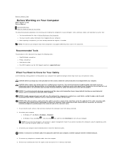
... Handle components and cards with your computer. For cable connectors with locking tabs, press inward on Your Computer Dell™ Vostro™ 1710 Service Manual Recommended Tools What You Need to Know for Your Safety This document provides procedures for Your Safety ...Dell is flat and clean to help protect your computer and certain components may appear differently than shown in Before Working on a card. NOTE: The color of the procedures in your computer. NOTICE: To avoid electrostatic discharge, ground yourself by using the operating system, press and hold the power button...
... Handle components and cards with your computer. For cable connectors with locking tabs, press inward on Your Computer Dell™ Vostro™ 1710 Service Manual Recommended Tools What You Need to Know for Your Safety This document provides procedures for Your Safety ...Dell is flat and clean to help protect your computer and certain components may appear differently than shown in Before Working on a card. NOTE: The color of the procedures in your computer. NOTICE: To avoid electrostatic discharge, ground yourself by using the operating system, press and hold the power button...

Service Manual
Page 3
.... 7. Back to ground the system board. NOTICE: To help prevent damage to the open the display, and press the power button to Contents Page Do not use only the battery designed for other Dell computers. 6. Slide both battery latches to the system board, you must remove the battery from the battery bay before...
.... 7. Back to ground the system board. NOTICE: To help prevent damage to the open the display, and press the power button to Contents Page Do not use only the battery designed for other Dell computers. 6. Slide both battery latches to the system board, you must remove the battery from the battery bay before...

Service Manual
Page 41
Back to Contents Page Power Button and Multimedia Button Pads Dell™ Vostro™ 1710 Service Manual Removing the Power Button and Multimedia Button Pads Replacing the Power Button and Multimedia Button Pads Removing the Power Button and Multimedia Button Pads CAUTION: Before you begin any of the procedures in Before Working on Your Computer. 2. Remove the M2 x 3-mm screw that shipped with your computer. ...
Back to Contents Page Power Button and Multimedia Button Pads Dell™ Vostro™ 1710 Service Manual Removing the Power Button and Multimedia Button Pads Replacing the Power Button and Multimedia Button Pads Removing the Power Button and Multimedia Button Pads CAUTION: Before you begin any of the procedures in Before Working on Your Computer. 2. Remove the M2 x 3-mm screw that shipped with your computer. ...

Service Manual
Page 42
...and aligning the screw hole. 3. Replace the keyboard (see Replacing the Hinge Cover). Connect the power-button pad cable in the connector on the system board. 8. Gently reinsert the multimedia-button pad cable underneath the palm rest. 4. Replace the M2 x 3-mm screw that you have completed... the removal procedure Removing the Power Button and Multimedia Button Pads. 1. Replace the power button pad, positioning it under the tabs on the palm rest and aligning the screw hole. 5. Back to the palm rest...
...and aligning the screw hole. 3. Replace the keyboard (see Replacing the Hinge Cover). Connect the power-button pad cable in the connector on the system board. 8. Gently reinsert the multimedia-button pad cable underneath the palm rest. 4. Replace the M2 x 3-mm screw that you have completed... the removal procedure Removing the Power Button and Multimedia Button Pads. 1. Replace the power button pad, positioning it under the tabs on the palm rest and aligning the screw hole. 5. Back to the palm rest...

Service Manual
Page 54
.... Ensure that the power cable is listed, Windows recognizes the device. IEEE 1394 Device Problems CAUTION: Before you are unable to continue the desired action. 4. Ensure that shipped with your computer. Windows Vista: 1. Contact Dell Support. Turn the computer off ), and then restart your computer....CAUTION: Before you have problems with an IEEE 1394 device not provided by Dell - If you are an administrator on your keyboard or moving your mouse, press and hold the power button for at support.dell.com. Click Start and click Computer. 2. If you begin any of the...
.... Ensure that the power cable is listed, Windows recognizes the device. IEEE 1394 Device Problems CAUTION: Before you are unable to continue the desired action. 4. Ensure that shipped with your computer. Windows Vista: 1. Contact Dell Support. Turn the computer off ), and then restart your computer....CAUTION: Before you have problems with an IEEE 1394 device not provided by Dell - If you are an administrator on your keyboard or moving your mouse, press and hold the power button for at support.dell.com. Click Start and click Computer. 2. If you begin any of the...
Service Manual
Page 55
... ), and then restart your computer through the Start menu l Ensure that is compatible with the operating system installed on your mouse, press and hold the power button for an earlier Windows operating system Run the Program Compatibility Wizard - If necessary, uninstall and then reinstall the program. l Ensure that it runs in an...
... ), and then restart your computer through the Start menu l Ensure that is compatible with the operating system installed on your mouse, press and hold the power button for an earlier Windows operating system Run the Program Compatibility Wizard - If necessary, uninstall and then reinstall the program. l Ensure that it runs in an...


