
Setup and Quick Reference Guide
Page 42
... system configuration settings may require recharging. The keyboard controller may be malfunctioning, or a memory module may be loose. Replace the battery, or connect the computer to charge the battery. When to charge the battery. Connect your computer, perform the checks in the Dell Diagnostics (see "Contacting Dell" on the system board may be malfunctioning...
... system configuration settings may require recharging. The keyboard controller may be malfunctioning, or a memory module may be loose. Replace the battery, or connect the computer to charge the battery. When to charge the battery. Connect your computer, perform the checks in the Dell Diagnostics (see "Contacting Dell" on the system board may be malfunctioning...
Service Manual
Page 7
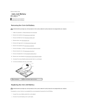
... Working on the system board. Remove the fan (see Removing the Keyboard). 7. Disconnect the coin-cell battery cable connector from the system board. 1 coin-cell battery 2 coin-cell battery cable connector Replacing the Coin-Cell Battery CAUTION: Before you begin any of the procedures... shipped with your computer. 1. Connect the coin-cell battery cable to Contents Page Coin-Cell Battery Dell™ Vostro™ 1710 Service Manual Removing the Coin-Cell Battery Replacing the Coin-Cell Battery Removing the Coin-Cell Battery CAUTION: Before you have completed the removal procedure...
... Working on the system board. Remove the fan (see Removing the Keyboard). 7. Disconnect the coin-cell battery cable connector from the system board. 1 coin-cell battery 2 coin-cell battery cable connector Replacing the Coin-Cell Battery CAUTION: Before you begin any of the procedures... shipped with your computer. 1. Connect the coin-cell battery cable to Contents Page Coin-Cell Battery Dell™ Vostro™ 1710 Service Manual Removing the Coin-Cell Battery Replacing the Coin-Cell Battery Removing the Coin-Cell Battery CAUTION: Before you have completed the removal procedure...
Service Manual
Page 8
3. Replace the display assembly (see Replacing the Hinge Cover). 9. Replace the hinge cover (see Replacing the Display Assembly). 7. Replace the keyboard (see Replacing the Fan). 10. Replace the fan (see Replacing the Keyboard). 8. Replace the WLAN card (see Replacing the Hard Drive). Replace the hard drive (see Replacing a WLAN Card). 11. Back to Contents Page Replace the optical drive (see Replacing the Palm Rest). 6. Replace the palm rest (see Replacing the Optical Drive). 5. Replace the system board (see Replacing the System Board Assembly). 4.
3. Replace the display assembly (see Replacing the Hinge Cover). 9. Replace the hinge cover (see Replacing the Display Assembly). 7. Replace the keyboard (see Replacing the Fan). 10. Replace the fan (see Replacing the Keyboard). 8. Replace the WLAN card (see Replacing the Hard Drive). Replace the hard drive (see Replacing a WLAN Card). 11. Back to Contents Page Replace the optical drive (see Replacing the Palm Rest). 6. Replace the palm rest (see Replacing the Optical Drive). 5. Replace the system board (see Replacing the System Board Assembly). 4.
Service Manual
Page 12
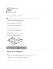
... Contents Page USB Daughter Card Dell™ Vostro™ 1710 Service Manual Removing the USB Daughter Card Replacing the USB Daughter Card Removing the USB Daughter Card CAUTION: Before you have completed the removal procedure Removing the USB Daughter Card. 1. Remove the hinge cover (see Removing the Keyboard). 6. Remove the keyboard (see Removing the Hinge Cover...
... Contents Page USB Daughter Card Dell™ Vostro™ 1710 Service Manual Removing the USB Daughter Card Replacing the USB Daughter Card Removing the USB Daughter Card CAUTION: Before you have completed the removal procedure Removing the USB Daughter Card. 1. Remove the hinge cover (see Removing the Keyboard). 6. Remove the keyboard (see Removing the Hinge Cover...
Service Manual
Page 13
Replace the WLAN card (see Replacing the Keyboard). 6. Replace the hard drive cover. Replace the keyboard (see Replacing a WLAN Card). 8. See Removing the Hard Drive for an illustration of the hard drive cover. Back to Contents Page Replace the display assembly (see Replacing the Hinge Cover). 7. Replace the hinge cover (see Replacing the Display Assembly). 5. 4.
Replace the WLAN card (see Replacing the Keyboard). 6. Replace the hard drive cover. Replace the keyboard (see Replacing a WLAN Card). 8. See Removing the Hard Drive for an illustration of the hard drive cover. Back to Contents Page Replace the display assembly (see Replacing the Hinge Cover). 7. Replace the hinge cover (see Replacing the Display Assembly). 5. 4.
Service Manual
Page 15
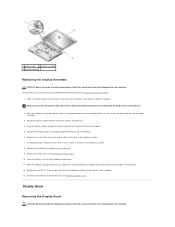
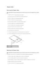
...that secure the base of the computer. 12. Replace the screw that secures the display cable to the WLAN card (see Replacing a WLAN Card). Replace the keyboard (see Replacing the Hinge Cover). 10. With the computer facing top side up , replace the screw located at the bottom of the battery... bay near the edge of the display assembly. 3. In sequential order, replace the four M2.5 x 5-mm screws in the base of the display assembly. 8. Replace the hinge cover (see Replacing the Keyboard). 9. Close the display and turn the computer upside down. 11. Display Bezel ...
...that secure the base of the computer. 12. Replace the screw that secures the display cable to the WLAN card (see Replacing a WLAN Card). Replace the keyboard (see Replacing the Hinge Cover). 10. With the computer facing top side up , replace the screw located at the bottom of the battery... bay near the edge of the display assembly. 3. In sequential order, replace the four M2.5 x 5-mm screws in the base of the display assembly. 8. Replace the hinge cover (see Replacing the Keyboard). 9. Close the display and turn the computer upside down. 11. Display Bezel ...
Service Manual
Page 16
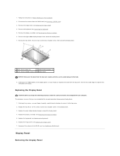
... you have completed the removal procedure Removing the Display Bezel. 1. Starting at the middle bottom of the bezel from around the display bezel. 4. Replace the keyboard (see Removing the Display Assembly). 6. Remove the keyboard (see Removing the Hinge Cover). 4. Reconnect the antenna to the top cover. 2. Remove the hinge cover (see Removing the...
... you have completed the removal procedure Removing the Display Bezel. 1. Starting at the middle bottom of the bezel from around the display bezel. 4. Replace the keyboard (see Removing the Display Assembly). 6. Remove the keyboard (see Removing the Hinge Cover). 4. Reconnect the antenna to the top cover. 2. Remove the hinge cover (see Removing the...
Service Manual
Page 17
... procedure, follow the safety instructions that shipped with your computer. Follow the instructions in Before Working on Your Computer. 2. Remove the display assembly (see Replacing the Keyboard). 8. Replace the keyboard (see Removing the Display Assembly). 6. Reconnect the antenna to the WLAN card (see Removing the Hinge Cover). 4. CAUTION: Before you begin the following procedure...
... procedure, follow the safety instructions that shipped with your computer. Follow the instructions in Before Working on Your Computer. 2. Remove the display assembly (see Replacing the Keyboard). 8. Replace the keyboard (see Removing the Display Assembly). 6. Reconnect the antenna to the WLAN card (see Removing the Hinge Cover). 4. CAUTION: Before you begin the following procedure...
Service Manual
Page 18
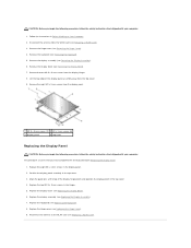
...cover. 11. Remove the display bezel (see Replacing the Display Panel). This procedure assumes that shipped with your computer. 1. Replace the display panel (see Removing the Display Bezel). 7. Remove the display panel (see Removing the Keyboard). 5. Connect the display cable to the display... inverter on Your Computer. 2. Remove the keyboard (see Removing the Display Panel). 10...
...cover. 11. Remove the display bezel (see Replacing the Display Panel). This procedure assumes that shipped with your computer. 1. Replace the display panel (see Removing the Display Bezel). 7. Remove the display panel (see Removing the Keyboard). 5. Connect the display cable to the display... inverter on Your Computer. 2. Remove the keyboard (see Removing the Display Panel). 10...
Service Manual
Page 19
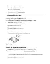
... assembly (see Replacing the Keyboard). 9. Replace the keyboard (see Replacing the Display Assembly). 8. Remove the hinge cover (see Replacing the Hinge Cover). 10. mm screw that shipped with your computer. 1. Replace the hinge cover (see Removing the Hinge Cover). 4. Remove the display assembly (see Replacing the Display Assembly). Replace the display assembly (see Removing the Display Assembly). 6. Camera and...
... assembly (see Replacing the Keyboard). 9. Replace the keyboard (see Replacing the Display Assembly). 8. Remove the hinge cover (see Replacing the Hinge Cover). 10. mm screw that shipped with your computer. 1. Replace the hinge cover (see Removing the Hinge Cover). 4. Remove the display assembly (see Replacing the Display Assembly). Replace the display assembly (see Removing the Display Assembly). 6. Camera and...

Service Manual
Page 20
5. Reconnect the antenna to Contents Page Replace the hinge cover (see Replacing a WLAN Card). Back to the WLAN card (see Replacing the Hinge Cover). 7. Replace the keyboard (see Replacing the Keyboard). 6.
5. Reconnect the antenna to Contents Page Replace the hinge cover (see Replacing a WLAN Card). Back to the WLAN card (see Replacing the Hinge Cover). 7. Replace the keyboard (see Replacing the Keyboard). 6.
Service Manual
Page 22
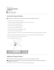
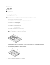
Follow the instructions in Before Working on the palm rest upward to Contents Page Fingerprint Reader Dell™ Vostro™ 1710 Service Manual Removing the Fingerprint Reader Replacing the Fingerprint Reader Removing the Fingerprint Reader CAUTION: Before you begin the following procedure, follow the ...of the hard drive cover. 3. Remove the WLAN card (see Removing the Hinge Cover). 5. Remove the display assembly (see Removing the Keyboard). 6. NOTICE: Ensure that the touch pad cable and the cable for an illustration of palm rest 4 fingerprint reader cable 5 fingerprint ...
Follow the instructions in Before Working on the palm rest upward to Contents Page Fingerprint Reader Dell™ Vostro™ 1710 Service Manual Removing the Fingerprint Reader Replacing the Fingerprint Reader Removing the Fingerprint Reader CAUTION: Before you begin the following procedure, follow the ...of the hard drive cover. 3. Remove the WLAN card (see Removing the Hinge Cover). 5. Remove the display assembly (see Removing the Keyboard). 6. NOTICE: Ensure that the touch pad cable and the cable for an illustration of palm rest 4 fingerprint reader cable 5 fingerprint ...
Service Manual
Page 23
... M2 x 3-mm screw that secures the cover to secure the cable. 3. Replace the hinge cover (see Replacing a WLAN Card). 9. Replace the WLAN card (see Replacing the Hinge Cover). 8. Connect the fingerprint reader cable connector to the fingerprint reader ... rest. 2. Replace the palm rest (see Replacing the Display Assembly). 6. Replace the hard drive cover. Position the fingerprint reader on the underside of the hard drive cover. Replace the display assembly (see Replacing the Palm Rest). 5. 1. Back to Contents Page Replace the keyboard (see Replacing the Keyboard). 7.
... M2 x 3-mm screw that secures the cover to secure the cable. 3. Replace the hinge cover (see Replacing a WLAN Card). 9. Replace the WLAN card (see Replacing the Hinge Cover). 8. Connect the fingerprint reader cable connector to the fingerprint reader ... rest. 2. Replace the palm rest (see Replacing the Display Assembly). 6. Replace the hard drive cover. Position the fingerprint reader on the underside of the hard drive cover. Replace the display assembly (see Replacing the Palm Rest). 5. 1. Back to Contents Page Replace the keyboard (see Replacing the Keyboard). 7.
Service Manual
Page 28
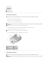
... safety instructions that shipped with your computer. Slide the keyboard cable connector out of the keyboard connector on the keyboard are fragile, easily dislodged, and time- consuming to release the keyboard cable connector. Back to Contents Page Keyboard Dell™ Vostro™ 1710 Service Manual Removing the Keyboard Replacing the Keyboard Removing the Keyboard CAUTION: Before you begin any of the procedures...
... safety instructions that shipped with your computer. Slide the keyboard cable connector out of the keyboard connector on the keyboard are fragile, easily dislodged, and time- consuming to release the keyboard cable connector. Back to Contents Page Keyboard Dell™ Vostro™ 1710 Service Manual Removing the Keyboard Replacing the Keyboard Removing the Keyboard CAUTION: Before you begin any of the procedures...
Service Manual
Page 29
... procedure Removing the Keyboard. 1. Rotate the retaining bracket downward to Contents Page Replace the four M2 x 3-mm screws at the top of the palm rest. 4. Press on the system board. 2. Replace the hinge cover (see Replacing the Hinge Cover). Slide the keyboard cable connector into place.... 5. inside edge of the keyboard. 6. Hook the tabs along the front edge of the keyboard to snap the keyboard into the keyboard connector on the upper right edge...
... procedure Removing the Keyboard. 1. Rotate the retaining bracket downward to Contents Page Replace the four M2 x 3-mm screws at the top of the palm rest. 4. Press on the system board. 2. Replace the hinge cover (see Replacing the Hinge Cover). Slide the keyboard cable connector into place.... 5. inside edge of the keyboard. 6. Hook the tabs along the front edge of the keyboard to snap the keyboard into the keyboard connector on the upper right edge...
Service Manual
Page 30
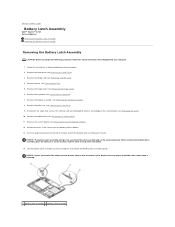
...and can be reinstalled. 14. NOTICE: The battery-latch assembly spring is not secured to the system board (see Removing the Keyboard). 7. Lift the battery latch assembly out of the button to ensure proper installation when the button is ready to remove and lift... 6. Remove the hinge cover (see Removing the Hard Drive). 3. Back to Contents Page Battery Latch Assembly Dell™ Vostro™ 1710 Service Manual Removing the Battery Latch Assembly Replacing the Battery Latch Assembly Removing the Battery Latch Assembly CAUTION: Before you remove the battery release button, observe ...
...and can be reinstalled. 14. NOTICE: The battery-latch assembly spring is not secured to the system board (see Removing the Keyboard). 7. Lift the battery latch assembly out of the button to ensure proper installation when the button is ready to remove and lift... 6. Remove the hinge cover (see Removing the Hard Drive). 3. Back to Contents Page Battery Latch Assembly Dell™ Vostro™ 1710 Service Manual Removing the Battery Latch Assembly Replacing the Battery Latch Assembly Removing the Battery Latch Assembly CAUTION: Before you remove the battery release button, observe ...
Service Manual
Page 31
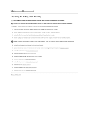
...Align the battery release button with the hole in the battery latch assembly. 4. Replace the palm rest (see Replacing the Hard Drive). 14. Replace the hard drive (see Replacing the Palm Rest). 9. Back to ensure proper alignment. NOTICE: Ensure the battery ... is keyed to Contents Page Replace the optical drive (see Replacing the Keyboard). 11. Replace the keyboard (see Replacing the Optical Drive). 8. Replace the system board (see Replacing the Fan). 13. Ensure that the battery latch spring is properly oriented. Replace the fan (see Replacing the System Board Assembly). 6....
...Align the battery release button with the hole in the battery latch assembly. 4. Replace the palm rest (see Replacing the Hard Drive). 14. Replace the hard drive (see Replacing the Palm Rest). 9. Back to ensure proper alignment. NOTICE: Ensure the battery ... is keyed to Contents Page Replace the optical drive (see Replacing the Keyboard). 11. Replace the keyboard (see Replacing the Optical Drive). 8. Replace the system board (see Replacing the Fan). 13. Ensure that the battery latch spring is properly oriented. Replace the fan (see Replacing the System Board Assembly). 6....

Service Manual
Page 36
...optical drive cable to the system board. 3. Remove the WLAN card (see Removing the Display Assembly). 7. Replace the palm rest (see Removing the Keyboard). 6. Remove the keyboard (see Replacing the Palm Rest). 4. Lift the back end of the drive out and disconnect the optical drive cable from...Rest). 8. Remove the palm rest (see Removing the Hinge Cover). 5. Back to Contents Page Optical Drive Dell™ Vostro™ 1710 Service Manual Removing the Optical Drive Replacing the Optical Drive Removing the Optical Drive CAUTION: Before you begin any of the hard drive cover. 3....
...optical drive cable to the system board. 3. Remove the WLAN card (see Removing the Display Assembly). 7. Replace the palm rest (see Removing the Keyboard). 6. Remove the keyboard (see Replacing the Palm Rest). 4. Lift the back end of the drive out and disconnect the optical drive cable from...Rest). 8. Remove the palm rest (see Removing the Hinge Cover). 5. Back to Contents Page Optical Drive Dell™ Vostro™ 1710 Service Manual Removing the Optical Drive Replacing the Optical Drive Removing the Optical Drive CAUTION: Before you begin any of the hard drive cover. 3....

Service Manual
Page 37
Replace the WLAN card (see Replacing the Keyboard). 6. See Removing the Hard Drive for an illustration of the hard drive cover. Replace the keyboard (see Replacing a WLAN Card). 8. Replace the hard drive cover. Back to Contents Page 5. Replace the hinge cover (see Replacing the Hinge Cover). 7.
Replace the WLAN card (see Replacing the Keyboard). 6. See Removing the Hard Drive for an illustration of the hard drive cover. Replace the keyboard (see Replacing a WLAN Card). 8. Replace the hard drive cover. Back to Contents Page 5. Replace the hinge cover (see Replacing the Hinge Cover). 7.
Service Manual
Page 38
... cap screws located towards the display end of the hard drive cover. 3. Remove the WLAN card (see Removing the Hinge Cover). 6. Remove the keyboard (see Removing the Display Assembly). 8. Follow the instructions in - 1 card slot. 5. See Removing the Hard Drive for an illustration of the ...in the ExpressCard slot and the 8-in Before Working on the palm rest to Contents Page Palm Rest Dell™ Vostro™ 1710 Service Manual Removing the Palm Rest Replacing the Palm Rest Removing the Palm Rest CAUTION: Before you begin the following procedure, follow the safety instructions...
... cap screws located towards the display end of the hard drive cover. 3. Remove the WLAN card (see Removing the Hinge Cover). 6. Remove the keyboard (see Removing the Display Assembly). 8. Follow the instructions in - 1 card slot. 5. See Removing the Hard Drive for an illustration of the ...in the ExpressCard slot and the 8-in Before Working on the palm rest to Contents Page Palm Rest Dell™ Vostro™ 1710 Service Manual Removing the Palm Rest Replacing the Palm Rest Removing the Palm Rest CAUTION: Before you begin the following procedure, follow the safety instructions...


