
Service Manual
Page 2
... procedure assumes that the computer and all open programs before you turn off your computer. Damage due to servicing that shipped with locking tabs; Turn off . Back to Contents Page Before You Begin Dell Studio™ 540 Service Manual Technical Specifications Recommended Tools Turning Off Your Computer Safety Instructions This chapter provides procedures for about...
... procedure assumes that the computer and all open programs before you turn off your computer. Damage due to servicing that shipped with locking tabs; Turn off . Back to Contents Page Before You Begin Dell Studio™ 540 Service Manual Technical Specifications Recommended Tools Turning Off Your Computer Safety Instructions This chapter provides procedures for about...
Service Manual
Page 4
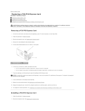
... Follow the procedures in the empty card-slot opening. 9. If necessary, disconnect any cables connected to electrical outlets, and then turn them on. 11. NOTICE: Installing filler brackets over empty card-slot openings is necessary to maintain FCC certification of Installing a ... card's driver and software from the operating system. See Replacing the Computer Cover. Back to Contents Page Replacing a PCI/PCI Express Card Dell Studio™ 540 Service Manual Removing a PCI/PCI Express Card Installing a PCI/PCI Express Card Replacing the Card Retention Bracket Configuring Your Computer ...
... Follow the procedures in the empty card-slot opening. 9. If necessary, disconnect any cables connected to electrical outlets, and then turn them on. 11. NOTICE: Installing filler brackets over empty card-slot openings is necessary to maintain FCC certification of Installing a ... card's driver and software from the operating system. See Replacing the Computer Cover. Back to Contents Page Replacing a PCI/PCI Express Card Dell Studio™ 540 Service Manual Removing a PCI/PCI Express Card Installing a PCI/PCI Express Card Replacing the Card Retention Bracket Configuring Your Computer ...

Service Manual
Page 5
... configuring, customizing and making internal connections on . 12. Remove the screw holding the card retention bracket. 4. Remove the filler bracket to electrical outlets, and then turn them on the card. 7.
... configuring, customizing and making internal connections on . 12. Remove the screw holding the card retention bracket. 4. Remove the filler bracket to electrical outlets, and then turn them on the card. 7.

Service Manual
Page 7
... battery from the battery and the battery will pop out. 6. Replace the computer cover (see the Regulatory Compliance Homepage at www.dell.com/regulatory_compliance. Discard used batteries according to Contents Page For additional safety best practices information, see Replacing the Computer Cover). 9. CAUTION... between the battery and the socket before you recorded in Before You Begin. 3. Back to Contents Page Replacing the Battery Dell Studio™ 540 Service Manual CAUTION: Before working inside your computer, read the safety information that shipped with your computer and ...
... battery from the battery and the battery will pop out. 6. Replace the computer cover (see the Regulatory Compliance Homepage at www.dell.com/regulatory_compliance. Discard used batteries according to Contents Page For additional safety best practices information, see Replacing the Computer Cover). 9. CAUTION... between the battery and the socket before you recorded in Before You Begin. 3. Back to Contents Page Replacing the Battery Dell Studio™ 540 Service Manual CAUTION: Before working inside your computer, read the safety information that shipped with your computer and ...

Service Manual
Page 10
NOTICE: You must position the processor correctly in the socket to avoid permanent damage to the processor and the computer when you turn them on the socket is aligned properly with the socket, and do not use excessive force when you install the processor. 12. Orient ...New thermal grease is critical for ensuring adequate thermal bonding, which is correctly seated and secure. 18. Be careful not to electrical outlets, and then turn on the socket. 11. Clean the thermal grease from the ATX POWER and ATX_CPU connectors (see System Board Components) on the system board. 19. ...
NOTICE: You must position the processor correctly in the socket to avoid permanent damage to the processor and the computer when you turn them on the socket is aligned properly with the socket, and do not use excessive force when you install the processor. 12. Orient ...New thermal grease is critical for ensuring adequate thermal bonding, which is correctly seated and secure. 18. Be careful not to electrical outlets, and then turn on the socket. 11. Clean the thermal grease from the ATX POWER and ATX_CPU connectors (see System Board Components) on the system board. 19. ...

Service Manual
Page 13
... drive: a. Replace the drive panel insert (see Replacing the Computer Cover). 3. Remove the two screws securing the CD/DVD drive to electrical outlets, and then turn them on. Align the four screw holes in the hard drive with the screw holes in your computer and will not replace it at this...
... drive: a. Replace the drive panel insert (see Replacing the Computer Cover). 3. Remove the two screws securing the CD/DVD drive to electrical outlets, and then turn them on. Align the four screw holes in the hard drive with the screw holes in your computer and will not replace it at this...

Service Manual
Page 14
... board (see the documentation that secure the FlexDock. Connect the FlexDock USB cable to the back of the FlexDock and to their electrical outlets, and turn them on the system board (see System Board Components). NOTE: If you installed a new drive, see System Board Components). 5. Remove the computer cover (see Replacing...
... board (see the documentation that secure the FlexDock. Connect the FlexDock USB cable to the back of the FlexDock and to their electrical outlets, and turn them on the system board (see System Board Components). NOTE: If you installed a new drive, see System Board Components). 5. Remove the computer cover (see Replacing...

Service Manual
Page 15
... locks in place. Remove the front panel (see Replacing the Front Panel). 14. Gently press on the insert lever outward to electrical outlets, and then turn them on the break-away metal plate and rotate the screwdriver outwards to break and remove the metal plate. Replace the front panel (see Replacing...
... locks in place. Remove the front panel (see Replacing the Front Panel). 14. Gently press on the insert lever outward to electrical outlets, and then turn them on the break-away metal plate and rotate the screwdriver outwards to break and remove the metal plate. Replace the front panel (see Replacing...

Service Manual
Page 17
11. Replace the computer cover (see Replacing a PCI/PCI Express Card). 12. Replace any expansion cards (see Replacing the Computer Cover). 14. Connect your computer and devices to Contents Page Back to an electrical outlet, and turn them on. Replace the front panel (see Replacing the Front Panel). 13.
11. Replace the computer cover (see Replacing a PCI/PCI Express Card). 12. Replace any expansion cards (see Replacing the Computer Cover). 14. Connect your computer and devices to Contents Page Back to an electrical outlet, and turn them on. Replace the front panel (see Replacing the Front Panel). 13.

Service Manual
Page 19
... that are routed over the processor fan and heat sink assembly. Connect the processor fan and heat sink assembly cable to an electrical outlet, and turn them on. New thermal grease is critical for the processor, do not touch the heat transfer areas on the system board (see System Board Components...
... that are routed over the processor fan and heat sink assembly. Connect the processor fan and heat sink assembly cable to an electrical outlet, and turn them on. New thermal grease is critical for the processor, do not touch the heat transfer areas on the system board (see System Board Components...

Service Manual
Page 21
... the screw that secures the I/O panel to the chassis. 10. Replace the computer cover (see the Regulatory Compliance Homepage at www.dell.com/regulatory_compliance. 1. An incorrectly routed or a disconnected cable could lead to Contents Page Back to computer problems. 5. For additional safety...the cables connected to Contents Page Replacing the Front I/O Panel Dell Studio™ 540 Service Manual CAUTION: Before working inside your computer, read the safety information that you are sure to an electrical outlet, and turn them on. Carefully remove the existing I/O panel from the ...
... the screw that secures the I/O panel to the chassis. 10. Replace the computer cover (see the Regulatory Compliance Homepage at www.dell.com/regulatory_compliance. 1. An incorrectly routed or a disconnected cable could lead to Contents Page Back to computer problems. 5. For additional safety...the cables connected to Contents Page Replacing the Front I/O Panel Dell Studio™ 540 Service Manual CAUTION: Before working inside your computer, read the safety information that you are sure to an electrical outlet, and turn them on. Carefully remove the existing I/O panel from the ...

Service Manual
Page 23
Connect your Microsoft®Windows® desktop and click Properties. 14. Click the General tab. 15. To verify that memory size has changed, press to Contents Page Back to continue. 12. Replace ... the module correctly, the securing clips snap into position. Right-click the My Computer icon on your computer and devices to electrical outlets, and then turn them on to each end of memory (RAM) listed. Log on . 11. If you apply equal force to your computer. 13.
Connect your Microsoft®Windows® desktop and click Properties. 14. Click the General tab. 15. To verify that memory size has changed, press to Contents Page Back to continue. 12. Replace ... the module correctly, the securing clips snap into position. Right-click the My Computer icon on your computer and devices to electrical outlets, and then turn them on to each end of memory (RAM) listed. Log on . 11. If you apply equal force to your computer. 13.
Service Manual
Page 24
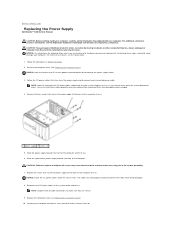
...remove them from being damaged. 8. Replace the computer cover (see Replacing the Computer Cover). Back to Contents Page Replacing the Power Supply Dell Studio™ 540 Service Manual CAUTION: Before working inside your computer, read the safety information that shipped with hardware removal and replacement. CAUTION:... computer. NOTE: Note the routing of the computer. Remove the four screws that secure the power supply to an electrical outlet, and turn them on. Slide the power supply towards the back of the DC power cables underneath the tabs in Before You Begin. 2. Connect...
...remove them from being damaged. 8. Replace the computer cover (see Replacing the Computer Cover). Back to Contents Page Replacing the Power Supply Dell Studio™ 540 Service Manual CAUTION: Before working inside your computer, read the safety information that shipped with hardware removal and replacement. CAUTION:... computer. NOTE: Note the routing of the computer. Remove the four screws that secure the power supply to an electrical outlet, and turn them on. Slide the power supply towards the back of the DC power cables underneath the tabs in Before You Begin. 2. Connect...

Service Manual
Page 28
Replace the processor and the heat sink assembly (see Installing a PCI/PCI Express Card). 17. Flash the system BIOS, as needed. Back to an electrical outlet, and turn them on. 19. NOTICE: Ensure that the heat sink assembly is correctly seated and secure. 16. Replace any expansion cards on flashing the system BIOS, see Replacing the Computer Cover). 18. NOTE: For information on the system board (see Replacing the Processor). Connect your computer and devices to Contents Page Replace the computer cover (see Flashing the BIOS. 15.
Replace the processor and the heat sink assembly (see Installing a PCI/PCI Express Card). 17. Flash the system BIOS, as needed. Back to an electrical outlet, and turn them on. 19. NOTICE: Ensure that the heat sink assembly is correctly seated and secure. 16. Replace any expansion cards on flashing the system BIOS, see Replacing the Computer Cover). 18. NOTE: For information on the system board (see Replacing the Processor). Connect your computer and devices to Contents Page Replace the computer cover (see Flashing the BIOS. 15.

Service Manual
Page 29
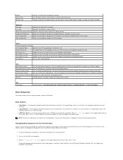
...NOTE: Depending on (or restart) your computer (see the Microsoft® Windows® desktop. Main System Date System Time SATA0 SATA1 SATA2 SATA3 SATA4 Displays current date settings, ... divided into three areas: the options list, active options field, and key functions. Turn on your computer and installed devices, the items listed in Options List. Information on ... the option's current and available settings. Help - Back to Contents Page System Setup Dell Studio™ 540 Service Manual Overview Clearing Forgotten Passwords Clearing CMOS Settings Flashing the BIOS Overview...
...NOTE: Depending on (or restart) your computer (see the Microsoft® Windows® desktop. Main System Date System Time SATA0 SATA1 SATA2 SATA3 SATA4 Displays current date settings, ... divided into three areas: the options list, active options field, and key functions. Turn on your computer and installed devices, the items listed in Options List. Information on ... the option's current and available settings. Help - Back to Contents Page System Setup Dell Studio™ 540 Service Manual Overview Clearing Forgotten Passwords Clearing CMOS Settings Flashing the BIOS Overview...
Service Manual
Page 30
... shut down your system. CD/DVD Boot Priority Sets the CD/DVD drive boot priority. Turn on the Drivers and Utilities media. Security Provides options to enable, disable or change the current... boot sequence, for example, to boot from the CD/DVD drive to run the Dell Diagnostics on (or restart) your device is on the computer automatically (0:00:00 by default...to change the passwords. AC Recovery Off; USB Configuration Allows you see the Microsoft Windows desktop. Power Power Management Setup ACPI Suspend Type Specifies the ACPI suspend type. On; Boot...
... shut down your system. CD/DVD Boot Priority Sets the CD/DVD drive boot priority. Turn on the Drivers and Utilities media. Security Provides options to enable, disable or change the current... boot sequence, for example, to boot from the CD/DVD drive to run the Dell Diagnostics on (or restart) your device is on the computer automatically (0:00:00 by default...to change the passwords. AC Recovery Off; USB Configuration Allows you see the Microsoft Windows desktop. Power Power Management Setup ACPI Suspend Type Specifies the ACPI suspend type. On; Boot...

Service Manual
Page 31
... want to enable the password feature. 7. Replace the computer cover (see System Board Components). 4. Follow the procedures in case you want to electrical outlets, and turn them on the system board (see Replacing the Computer Cover). 8. Press plus (+) or minus (-) to access the menu.
... want to enable the password feature. 7. Replace the computer cover (see System Board Components). 4. Follow the procedures in case you want to electrical outlets, and turn them on the system board (see Replacing the Computer Cover). 8. Press plus (+) or minus (-) to access the menu.

Service Manual
Page 32
...Save this Agreement. Remove the jumper plug and replace it on the CMOS jumper (CLEAR_CMOS) pins 2 and 3 and wait approximately five seconds. 6. Turn on the system board (see Replacing the Computer Cover). 3. Locate the BIOS update file for your computer. 3. Clearing CMOS Settings CAUTION: Before you... then locate the BIOS update file for your computer at the Dell Support website at the bottom of the procedures in Before You Begin. 2. CAUTION: The computer must be disconnected from the drop-down arrow to your desktop. 7. Locate the 3-pin CMOS jumper (CLEAR_CMOS) on the ...
...Save this Agreement. Remove the jumper plug and replace it on the CMOS jumper (CLEAR_CMOS) pins 2 and 3 and wait approximately five seconds. 6. Turn on the system board (see Replacing the Computer Cover). 3. Locate the BIOS update file for your computer. 3. Clearing CMOS Settings CAUTION: Before you... then locate the BIOS update file for your computer at the Dell Support website at the bottom of the procedures in Before You Begin. 2. CAUTION: The computer must be disconnected from the drop-down arrow to your desktop. 7. Locate the 3-pin CMOS jumper (CLEAR_CMOS) on the ...
Setup Guide
Page 17
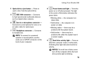
...on state. • Blinking amber - NOTE: To connect to an audio cable for audio input. 7 Headphone connector - Using Your Studio 540 8 Power button and light - Turns the power on when the computer reads or writes data. there may be a problem with either the system board or power supply..... Press to eject a disc from the optical drive. 5 IEEE 1394 connector - the computer is in the center of data, never turn off when pressed. 4 Optical drive eject button - Turns on or off the computer while the hard drive activity light is in or microphone connector -
...on state. • Blinking amber - NOTE: To connect to an audio cable for audio input. 7 Headphone connector - Using Your Studio 540 8 Power button and light - Turns the power on when the computer reads or writes data. there may be a problem with either the system board or power supply..... Press to eject a disc from the optical drive. 5 IEEE 1394 connector - the computer is in the center of data, never turn off when pressed. 4 Optical drive eject button - Turns on or off the computer while the hard drive activity light is in or microphone connector -

Setup Guide
Page 25
...the computer is plugged into a power strip, ensure that the power strip is plugged into an electrical outlet and that your connection is turned on the integrated network connector lets you verify that the power strip is working by testing it is lost - The link integrity light ... the power light is only for wireless connections. Also bypass power protection devices, power strips, and power extension cables to verify that the computer turns on the status: • Green - The computer is working and provides information on properly. • Ensure that the electrical outlet is not...
...the computer is plugged into a power strip, ensure that the power strip is plugged into an electrical outlet and that your connection is turned on the integrated network connector lets you verify that the power strip is working by testing it is lost - The link integrity light ... the power light is only for wireless connections. Also bypass power protection devices, power strips, and power extension cables to verify that the computer turns on the status: • Green - The computer is working and provides information on properly. • Ensure that the electrical outlet is not...

