
Hardware Manual
Page 11
...provide access to configure NIC settings for PXE boot. Enters the BIOS Boot Manager or the UEFI Boot Manager, depending on your SAS controller. Enters PXE boot, if enabled. See the iDRAC user documentation for your system's boot configuration. For more information, see the ...documentation for more information. NOTE: Some Unified Server Configurator processing, such as software updates, can access utilities such as USB devices attached to...
...provide access to configure NIC settings for PXE boot. Enters the BIOS Boot Manager or the UEFI Boot Manager, depending on your SAS controller. Enters PXE boot, if enabled. See the iDRAC user documentation for your system's boot configuration. For more information, see the ...documentation for more information. NOTE: Some Unified Server Configurator processing, such as software updates, can access utilities such as USB devices attached to...
Hardware Manual
Page 41
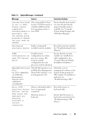
... set in BIOS and the compatible boot operating system is bootable media is set correctly and that mouse and keyboard are installed in BIOS. Check the system management software or the System Setup program for each CPU should match. See "Troubleshooting a USB Device." available. See "Troubleshooting System Memory." The memory module configuration...
... set in BIOS and the compatible boot operating system is bootable media is set correctly and that mouse and keyboard are installed in BIOS. Check the system management software or the System Setup program for each CPU should match. See "Troubleshooting a USB Device." available. See "Troubleshooting System Memory." The memory module configuration...
Hardware Manual
Page 42
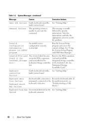
... the System Setup program and review the current settings. See "Using the System Setup Program and UEFI Boot Manager." Remove the PCIe expansion card and install the integrated storage controller in the Internal_Storage slot! "Troubleshooting a USB Device." Table 1-2. Note the information, and take the appropriate action to carry out the command. See...
... the System Setup program and review the current settings. See "Using the System Setup Program and UEFI Boot Manager." Remove the PCIe expansion card and install the integrated storage controller in the Internal_Storage slot! "Troubleshooting a USB Device." Table 1-2. Note the information, and take the appropriate action to carry out the command. See...
Hardware Manual
Page 45
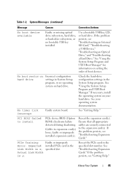
...Setup program, or no bootable USB key installed. If the problem persists, see "Troubleshooting an Internal SD Card," "Troubleshooting a USB Device," "Troubleshooting an Optical Drive," and "Troubleshooting a Hard Drive." Cables to the expansion card(s). No boot sector on your operating system ...See "Getting Help." If the problem persists, see "Troubleshooting Expansion Cards." See "Using the System Setup Program and UEFI Boot Manager" for information on hard drive. If necessary, install the operating system on Incorrect configuration hard drive settings in the Link...
...Setup program, or no bootable USB key installed. If the problem persists, see "Troubleshooting an Internal SD Card," "Troubleshooting a USB Device," "Troubleshooting an Optical Drive," and "Troubleshooting a Hard Drive." Cables to the expansion card(s). No boot sector on your operating system ...See "Getting Help." If the problem persists, see "Troubleshooting Expansion Cards." See "Using the System Setup Program and UEFI Boot Manager" for information on hard drive. If necessary, install the operating system on Incorrect configuration hard drive settings in the Link...
Hardware Manual
Page 56
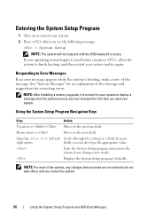
...Spacebar, , , left and Cycles through the settings in a field. NOTE: For most of the options, any changes were made. Responding to finish booting, and then restart your system. 2 Press after you can also type the appropriate value. If your operating system begins to load before you press , ... respond until you restart the system. 56 Using the System Setup Program and UEFI Boot Manager NOTE: After installing a memory upgrade, it is booting, make are recorded but do not take effect until the USB keyboard is active. Exits the System Setup program and restarts the system if any...
...Spacebar, , , left and Cycles through the settings in a field. NOTE: For most of the options, any changes were made. Responding to finish booting, and then restart your system. 2 Press after you can also type the appropriate value. If your operating system begins to load before you press , ... respond until you restart the system. 56 Using the System Setup Program and UEFI Boot Manager NOTE: After installing a memory upgrade, it is booting, make are recorded but do not take effect until the USB keyboard is active. Exits the System Setup program and restarts the system if any...
Hardware Manual
Page 61
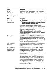
... set to BIOS, this option to UEFI disables the Boot Sequence, Hard-Disk Drive Sequence, and USB Flash Drive Emulation Type fields. Boot Settings Screen Option Boot Mode (BIOS default) Boot Sequence Hard-Disk Drive Sequence USB Flash Drive Emulation Type (Auto default) Description CAUTION: Switching the boot mode could prevent the system from hard drives in...
... set to BIOS, this option to UEFI disables the Boot Sequence, Hard-Disk Drive Sequence, and USB Flash Drive Emulation Type fields. Boot Settings Screen Option Boot Mode (BIOS default) Boot Sequence Hard-Disk Drive Sequence USB Flash Drive Emulation Type (Auto default) Description CAUTION: Switching the boot mode could prevent the system from hard drives in...
Hardware Manual
Page 62
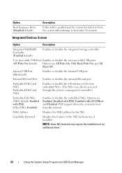
...Enabled default) Enables or disables the integrated storage controller. Internal USB Port (On default) Enables or disables the internal USB port. PXE support allows the system to boot after 30 seconds. Option Boot Sequence Retry (Disabled default) Description If this field is enabled ... NIC features may also be accessed through the system's management controller.) Embedded Gb NICx (NIC1 default: Enabled with iSCSI Boot, and Disabled. User Accessible USB Ports Enables or disables the user-accessible USB ports. (All Ports On default) Options are Enabled, Enabled with PXE,...
...Enabled default) Enables or disables the integrated storage controller. Internal USB Port (On default) Enables or disables the internal USB port. PXE support allows the system to boot after 30 seconds. Option Boot Sequence Retry (Disabled default) Description If this field is enabled ... NIC features may also be accessed through the system's management controller.) Embedded Gb NICx (NIC1 default: Enabled with iSCSI Boot, and Disabled. User Accessible USB Ports Enables or disables the user-accessible USB ports. (All Ports On default) Options are Enabled, Enabled with PXE,...
Hardware Manual
Page 68
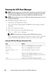
... enables you see the following message: = UEFI Boot Manager NOTE: The system will not respond until the USB keyboard is active. Using the UEFI Boot Manager Navigation Keys Keys Up arrow Down arrow Spacebar, Action Moves to and highlights the next field. If your operating system ...begins to load before you press , allow the system to finish booting, and then restart your system...
... enables you see the following message: = UEFI Boot Manager NOTE: The system will not respond until the USB keyboard is active. Using the UEFI Boot Manager Navigation Keys Keys Up arrow Down arrow Spacebar, Action Moves to and highlights the next field. If your operating system ...begins to load before you press , allow the system to finish booting, and then restart your system...
Hardware Manual
Page 91
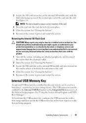
See "Closing the System." 5 Reconnect the system to power and restart the system. The USB connector must be done by Dell is keyed to ensure correct insertion of the card. 4 Press the card into the card slot to lock it from the electrical outlet. 2 Open the ... the Internal SD Flash Card CAUTION: Many repairs may only be enabled by the online or telephone service and support team. To boot from the USB memory key, configure the USB memory key with the product. 1 Turn off the system, including any attached peripherals, and disconnect the system from the slot and remove...
See "Closing the System." 5 Reconnect the system to power and restart the system. The USB connector must be done by Dell is keyed to ensure correct insertion of the card. 4 Press the card into the card slot to lock it from the electrical outlet. 2 Open the ... the Internal SD Flash Card CAUTION: Many repairs may only be enabled by the online or telephone service and support team. To boot from the USB memory key, configure the USB memory key with the product. 1 Turn off the system, including any attached peripherals, and disconnect the system from the slot and remove...
Hardware Manual
Page 164
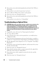
... connected to the drive and the system board. 10 Close the system. See "Using Dell™ PowerEdge™ Diagnostics." 6 Turn off the system and attached peripherals, and disconnect the system ...from the electrical outlet. 7 Open the system. See "Using the System Setup Program and UEFI Boot ...Closing the System." 10 Turn on the system and attached peripherals and check if the USB key is functioning. 7 If the problem is functioning. Troubleshooting an Optical Drive CAUTION:...
... connected to the drive and the system board. 10 Close the system. See "Using Dell™ PowerEdge™ Diagnostics." 6 Turn off the system and attached peripherals, and disconnect the system ...from the electrical outlet. 7 Open the system. See "Using the System Setup Program and UEFI Boot ...Closing the System." 10 Turn on the system and attached peripherals and check if the USB key is functioning. 7 If the problem is functioning. Troubleshooting an Optical Drive CAUTION:...
Hardware Manual
Page 201
battery (RAID) installing, 116 removing, 116 battery (system) replacing, 141 troubleshooting, 158 BIOS boot mode, 55 blank hard drive, 81 power supply, 88 boot mode, 55 C cable retention bracket installing, 119 removing, 118 cable routing, 118 cabling cable routing, 118 optical drive, 103 storage ...expansion-card riser 1, 185 expansion-card riser 2, 186-187 NIC, 20 SAS backplane board, 182 serial, 20 system board, 180 USB, 12 video, 12 contacting Dell, 189 control panel assembly features, 12 LCD panel features, 15 control panel board installing, 145 removing, 144 control panel display module ...
battery (RAID) installing, 116 removing, 116 battery (system) replacing, 141 troubleshooting, 158 BIOS boot mode, 55 blank hard drive, 81 power supply, 88 boot mode, 55 C cable retention bracket installing, 119 removing, 118 cable routing, 118 cabling cable routing, 118 optical drive, 103 storage ...expansion-card riser 1, 185 expansion-card riser 2, 186-187 NIC, 20 SAS backplane board, 182 serial, 20 system board, 180 USB, 12 video, 12 contacting Dell, 189 control panel assembly features, 12 LCD panel features, 15 control panel board installing, 145 removing, 144 control panel display module ...

Hardware Manual
Page 207
...107 removing, 110 troubleshooting, 165 TPM security, 66 troubleshooting cooling fans, 160 damaged system, 157 external connections, 153 hard drive, 166 internal USB memory key, 163 keyboard, 154 memory, 160 NIC, 155 optical drive, 164 PCIe expansion cards, 168 power supplies, 158 processor(s), 170 ... backup unit, 165 video, 154 wet system, 156 U UEFI Boot Manager entering, 68 main screen, 69 System Utilities screen, 69 UEFI Boot Settings screen, 69 UEFI boot mode, 55 upgrades processor, 137 USB back-panel connectors, 20 front-panel connectors, 12 USB cable internal installing, 93 removing, 93...
...107 removing, 110 troubleshooting, 165 TPM security, 66 troubleshooting cooling fans, 160 damaged system, 157 external connections, 153 hard drive, 166 internal USB memory key, 163 keyboard, 154 memory, 160 NIC, 155 optical drive, 164 PCIe expansion cards, 168 power supplies, 158 processor(s), 170 ... backup unit, 165 video, 154 wet system, 156 U UEFI Boot Manager entering, 68 main screen, 69 System Utilities screen, 69 UEFI Boot Settings screen, 69 UEFI boot mode, 55 upgrades processor, 137 USB back-panel connectors, 20 front-panel connectors, 12 USB cable internal installing, 93 removing, 93...
Technical Guide
Page 21
...boot and pre-boot OS for ease of deployment or diskless environments USB license keys for software applications like eToken™ or Sentinel Hardware Keys Storage of the USB key are also used to generate and store keys, protect and authenticate passwords, and create and store digital certificates. PowerEdge R710 Technical Guide 21 Dell...is opened . 4.11.7 Secure Mode BIOS has the ability to enter a secure boot mode through a BIOS option and uses HMAC-SHA1-160 for the Real-Time Clock and CMOS RAM on the bezel secures the switch behind the bezel. When the cover is used...
...boot and pre-boot OS for ease of deployment or diskless environments USB license keys for software applications like eToken™ or Sentinel Hardware Keys Storage of the USB key are also used to generate and store keys, protect and authenticate passwords, and create and store digital certificates. PowerEdge R710 Technical Guide 21 Dell...is opened . 4.11.7 Secure Mode BIOS has the ability to enter a secure boot mode through a BIOS option and uses HMAC-SHA1-160 for the Real-Time Clock and CMOS RAM on the bezel secures the switch behind the bezel. When the cover is used...
Technical Guide
Page 36
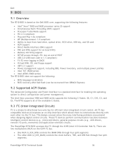
...the DIMM SPDs through four split segments The other via the I2C bus. The PowerEdge R710 BIOS accesses the I2C through the ICH9 (Intel I /O ports, memories) and application-oriented...concept solves the many interfacing problems encountered when designing digital control circuits. The R710 supports all of POST USB 2.0 (USB boot code is 1.1 compliant) F1/F2 error logging in CMOS &#...AESNI (5600 series) The R710 BIOS does not support the following C-States: C0, C1, C1E, C3, and C6. Dell 9 BIOS 9.1 Overview The R710 BIOS is based on the Dell BIOS core, supporting the...
...the DIMM SPDs through four split segments The other via the I2C bus. The PowerEdge R710 BIOS accesses the I2C through the ICH9 (Intel I /O ports, memories) and application-oriented...concept solves the many interfacing problems encountered when designing digital control circuits. The R710 supports all of POST USB 2.0 (USB boot code is 1.1 compliant) F1/F2 error logging in CMOS &#...AESNI (5600 series) The R710 BIOS does not support the following C-States: C0, C1, C1E, C3, and C6. Dell 9 BIOS 9.1 Overview The R710 BIOS is based on the Dell BIOS core, supporting the...


