
Hardware Manual
Page 7
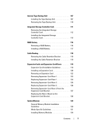
... 107 Installing the Tape Backup Unit 107 Removing the Tape Backup Unit 110 Integrated Storage Controller Card 111 Removing the Integrated Storage Controller Card 112 Installing the Integrated Storage Controller Card 112 RAID Battery 116 Removing a RAID Battery 116 Installing a RAID Battery 117 Cable Routing 118 Removing the Cable Retention Bracket 118 Installing the Cable Retention...
... 107 Installing the Tape Backup Unit 107 Removing the Tape Backup Unit 110 Integrated Storage Controller Card 111 Removing the Integrated Storage Controller Card 112 Installing the Integrated Storage Controller Card 112 RAID Battery 116 Removing a RAID Battery 116 Installing a RAID Battery 117 Cable Routing 118 Removing the Cable Retention Bracket 118 Installing the Cable Retention...
Hardware Manual
Page 24
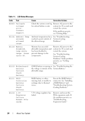
...failure. E1211 RAID Controller battery failure. Cause Corrective Actions Check the system event log Remove AC power to the system for critical failure events. Remove AC power to the for 10 seconds and restart the system. See "Troubleshooting System Cooling Problems." See "Installing a RAID Battery" and... or See "Troubleshooting the the voltage is either missing, bad, or unable to recharge due to the components. Reseat the RAID battery connector. LCD Status Messages Code Text E1000 Failsafe voltage error. Contact support. E1114 Ambient Temp exceeds allowed range. Power cycle...
...failure. E1211 RAID Controller battery failure. Cause Corrective Actions Check the system event log Remove AC power to the system for critical failure events. Remove AC power to the for 10 seconds and restart the system. See "Troubleshooting System Cooling Problems." See "Installing a RAID Battery" and... or See "Troubleshooting the the voltage is either missing, bad, or unable to recharge due to the components. Reseat the RAID battery connector. LCD Status Messages Code Text E1000 Failsafe voltage error. Contact support. E1114 Ambient Temp exceeds allowed range. Power cycle...
Hardware Manual
Page 36
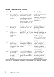
... for more power than what the power supply can provide, but it can display sequentially on the events. Warns predictively that the Allow RAID battery to RAID battery has less than charge to the system, reduce the hardware configuration or install higher-wattage power supplies, and then restart the system..... Table 1-1. Check SEL to log any more power than 24 24 hours of events and is unable to review all Errors. See "Installing a RAID Battery." Check PSU and system configuration. W1228 RAID Controller battery capacity < 24hr. If problem persists, replace the...
... for more power than what the power supply can provide, but it can display sequentially on the events. Warns predictively that the Allow RAID battery to RAID battery has less than charge to the system, reduce the hardware configuration or install higher-wattage power supplies, and then restart the system..... Table 1-1. Check SEL to log any more power than 24 24 hours of events and is unable to review all Errors. See "Installing a RAID Battery." Check PSU and system configuration. W1228 RAID Controller battery capacity < 24hr. If problem persists, replace the...
Hardware Manual
Page 62
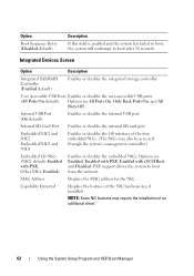
... allows the system to boot after 30 seconds. Integrated Devices Screen Option Description Integrated SAS/RAID Controller (Enabled default) Enables or disables the integrated storage controller. NOTE: Some NIC features may also be accessed through the system's management controller.) Embedded Gb NICx (NIC1 default: Enabled with iSCSI Boot, and Disabled. MAC Address Displays the MAC...
... allows the system to boot after 30 seconds. Integrated Devices Screen Option Description Integrated SAS/RAID Controller (Enabled default) Enables or disables the integrated storage controller. NOTE: Some NIC features may also be accessed through the system's management controller.) Embedded Gb NICx (NIC1 default: Enabled with iSCSI Boot, and Disabled. MAC Address Displays the MAC...
Hardware Manual
Page 76
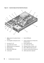
... hot-swappable cooling fans (4 or 5) 5 processors (1 or 2) 7 riser 2 (PCIe slots 3 and 4) 9 iDRAC6 Enterprise card (optional) 11 SAS backplane 13 RAID battery (PERC only) 15 control panel 2 Internal SD Module 4 memory modules (up to 18 total, 9 for each processor) 6 power supply bays (2) 8 riser 1 (PCIe slots 1 and 2) ...10 integrated storage controller card 12 SAS or SATA hard drives (up to 8) 14 flex bay for optional tape backup unit...
... hot-swappable cooling fans (4 or 5) 5 processors (1 or 2) 7 riser 2 (PCIe slots 3 and 4) 9 iDRAC6 Enterprise card (optional) 11 SAS backplane 13 RAID battery (PERC only) 15 control panel 2 Internal SD Module 4 memory modules (up to 18 total, 9 for each processor) 6 power supply bays (2) 8 riser 1 (PCIe slots 1 and 2) ...10 integrated storage controller card 12 SAS or SATA hard drives (up to 8) 14 flex bay for optional tape backup unit...
Hardware Manual
Page 82
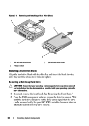
...-Drive Blank Align the hard-drive blank with your operating system supports hot-swap drive removal and installation. See "Removing the Front Bezel." 2 From the RAID management software, prepare the drive for information about hot-swap drive removal. 82 Installing System Components Wait until the release lever clicks into place. Removing... the hard-drive indicators on the drive carrier signal that your operating system for more information. 1 If present, remove the front bezel. See your SAS RAID controller documentation for removal. Figure 3-4.
...-Drive Blank Align the hard-drive blank with your operating system supports hot-swap drive removal and installation. See "Removing the Front Bezel." 2 From the RAID management software, prepare the drive for information about hot-swap drive removal. 82 Installing System Components Wait until the release lever clicks into place. Removing... the hard-drive indicators on the drive carrier signal that your operating system for more information. 1 If present, remove the front bezel. See your SAS RAID controller documentation for removal. Figure 3-4.
Hardware Manual
Page 111
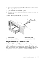
... Unit 1 2 3 4 1 tape backup unit 3 power cable for optical drive 2 interface/power cable 4 mounting tray release tab (2) Integrated Storage Controller Card Your system includes a dedicated expansion-card slot on the system. 8 Insert the assembled blank tray into the flex bay and slide the unit in... RAID configurations as supported by the version of the storage controller included with your system and peripherals to their electrical outlets, and turn on riser 1 for an integrated ...
... Unit 1 2 3 4 1 tape backup unit 3 power cable for optical drive 2 interface/power cable 4 mounting tray release tab (2) Integrated Storage Controller Card Your system includes a dedicated expansion-card slot on the system. 8 Insert the assembled blank tray into the flex bay and slide the unit in... RAID configurations as supported by the version of the storage controller included with your system and peripherals to their electrical outlets, and turn on riser 1 for an integrated ...
Hardware Manual
Page 112
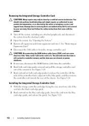
... shutdown. 5 If necessary, disconnect the RAID battery cable from a PERC card can cause data loss if the "dirty cache" LED on the card is not covered by Dell is lit. See "Opening the System." 3 Remove all expansion cards from the storage controller card. See Figure 3-20. See Figure...peripherals, and disconnect the system from the electrical outlet. 2 Open the system. CAUTION: Disconnecting the RAID battery cable from the controller. 6 Bend both card-edge guides outward and pull the storage controller card out of the card into the black card-edge guide. 2 Bend outward on both card...
... shutdown. 5 If necessary, disconnect the RAID battery cable from a PERC card can cause data loss if the "dirty cache" LED on the card is not covered by Dell is lit. See "Opening the System." 3 Remove all expansion cards from the storage controller card. See Figure 3-20. See Figure...peripherals, and disconnect the system from the electrical outlet. 2 Open the system. CAUTION: Disconnecting the RAID battery cable from the controller. 6 Bend both card-edge guides outward and pull the storage controller card out of the card into the black card-edge guide. 2 Bend outward on both card...
Hardware Manual
Page 113
... are not operational if reversed. 5 For a battery-cached PERC controller, install the RAID battery. Installing a Storage Controller Card 2 1 3 4 5 8 7 6 1 dedicated storage controller card connector 3 integrated storage controller card 5 SAS_1 connector 7 SAS_0 connector 2 riser 1 4 RAID battery connector (PERC only) 6 connector locking tabs 8 card edge guides (2) 3 Slide the storage controller's card edge connector into the card slot on the cable...
... are not operational if reversed. 5 For a battery-cached PERC controller, install the RAID battery. Installing a Storage Controller Card 2 1 3 4 5 8 7 6 1 dedicated storage controller card connector 3 integrated storage controller card 5 SAS_1 connector 7 SAS_0 connector 2 riser 1 4 RAID battery connector (PERC only) 6 connector locking tabs 8 card edge guides (2) 3 Slide the storage controller's card edge connector into the card slot on the cable...
Hardware Manual
Page 114
... done, route the interface and RAID battery cables in Hard-Drive Chassis) 1 2 3 45 6 78 1 RAID battery (PERC only) 3 SAS A connector on backplane 5 integrated storage controller card 7 SAS_1 connector 2 SAS B connector on backplane 4 cable retention bracket 6 SAS_0 connector 8 RAID battery connector (PERC only) 114 Installing System Components Figure 3-21. Storage Controller Card Cabling (2.5-in the cable...
... done, route the interface and RAID battery cables in Hard-Drive Chassis) 1 2 3 45 6 78 1 RAID battery (PERC only) 3 SAS A connector on backplane 5 integrated storage controller card 7 SAS_1 connector 2 SAS B connector on backplane 4 cable retention bracket 6 SAS_0 connector 8 RAID battery connector (PERC only) 114 Installing System Components Figure 3-21. Storage Controller Card Cabling (2.5-in the cable...
Hardware Manual
Page 115
Storage Controller Card Cabling (Six 3.5-in Hard-Drive Chassis) 1 2 3 45 6 78 1 RAID battery (PERC only) 3 SAS A connector on backplane 5 integrated storage controller card 7 SAS_1 connector 2 SAS B connector on backplane 4 cable retention bracket 6 SAS_0 connector 8 RAID battery connector (PERC only) Installing System Components 115 Figure 3-22.
Storage Controller Card Cabling (Six 3.5-in Hard-Drive Chassis) 1 2 3 45 6 78 1 RAID battery (PERC only) 3 SAS A connector on backplane 5 integrated storage controller card 7 SAS_1 connector 2 SAS B connector on backplane 4 cable retention bracket 6 SAS_0 connector 8 RAID battery connector (PERC only) Installing System Components 115 Figure 3-22.
Hardware Manual
Page 116
... the right edge of the battery bay and draw out the RAID battery from the battery carrier. 2 Disconnect the cable between the RAID battery and the storage controller card. Removing a RAID Battery 1 Pull back gently on backplane 4 integrated storage controller card 6 RAID battery connector (PERC only) RAID Battery The information in this section applies only to systems...
... the right edge of the battery bay and draw out the RAID battery from the battery carrier. 2 Disconnect the cable between the RAID battery and the storage controller card. Removing a RAID Battery 1 Pull back gently on backplane 4 integrated storage controller card 6 RAID battery connector (PERC only) RAID Battery The information in this section applies only to systems...
Hardware Manual
Page 117
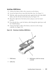
.... 5 If not already done, route the battery cable through the right chassis wall. Removing or Installing a RAID Battery 2 1 1 RAID battery 3 battery bay 3 2 RAID battery cable from storage controller Installing System Components 117 See "Cable Routing." 6 Connect the battery cable to the connector on the battery.... 2 Locate the battery bay on the storage controller. See Figure 3-20. Figure 3-24. See Figure 3-24. 4 Rotate the right side of the battery bay. Installing a RAID Battery 1 Connect the battery cable to the battery connector on top of the...
.... 5 If not already done, route the battery cable through the right chassis wall. Removing or Installing a RAID Battery 2 1 1 RAID battery 3 battery bay 3 2 RAID battery cable from storage controller Installing System Components 117 See "Cable Routing." 6 Connect the battery cable to the connector on the battery.... 2 Locate the battery bay on the storage controller. See Figure 3-20. Figure 3-24. See Figure 3-24. 4 Rotate the right side of the battery bay. Installing a RAID Battery 1 Connect the battery cable to the battery connector on top of the...
Hardware Manual
Page 151
...removed, reinstall the SAS backplane and all hard drives. See "Replacing Expansion-Card Riser 1" and "Replacing Expansion-Card Riser 2." 8 Reinstall the integrated storage controller card. See "Replacing the Fan Bracket." 15 Replace the cooling shroud. See "System Board." 12 Install all power and interface cables (see Figure 6-2 ... system board toward the back of the connectors on , including any attached peripherals. Installing System Components 151 See "Installing the Integrated Storage Controller Card." 9 If applicable, reconnect the RAID battery cable to the new system board.
...removed, reinstall the SAS backplane and all hard drives. See "Replacing Expansion-Card Riser 1" and "Replacing Expansion-Card Riser 2." 8 Reinstall the integrated storage controller card. See "Replacing the Fan Bracket." 15 Replace the cooling shroud. See "System Board." 12 Install all power and interface cables (see Figure 6-2 ... system board toward the back of the connectors on , including any attached peripherals. Installing System Components 151 See "Installing the Integrated Storage Controller Card." 9 If applicable, reconnect the RAID battery cable to the new system board.

Hardware Manual
Page 166
... resolved, see "Getting Help." You should only perform troubleshooting and simple repairs as authorized in a RAID array, perform the following steps. 2 Remove the bezel. See "Using Dell™ PowerEdge™ Diagnostics." See "Removing the Front Bezel." 3 If your warranty. b For SATA tape devices...needed through the following steps. Before you cannot resolve the problem, see the documentation for the tape drive for a SAS controller. CAUTION: This troubleshooting procedure can destroy data stored on the hard drive. 1 Run the appropriate online diagnostics test. See ...
... resolved, see "Getting Help." You should only perform troubleshooting and simple repairs as authorized in a RAID array, perform the following steps. 2 Remove the bezel. See "Using Dell™ PowerEdge™ Diagnostics." See "Removing the Front Bezel." 3 If your warranty. b For SATA tape devices...needed through the following steps. Before you cannot resolve the problem, see the documentation for the tape drive for a SAS controller. CAUTION: This troubleshooting procedure can destroy data stored on the hard drive. 1 Run the appropriate online diagnostics test. See ...
Hardware Manual
Page 167
...drive offline and then reseat the hard drive. See "Using Dell™ PowerEdge™ Diagnostics." 2 Enter the System Setup program and ensure that the hard drive(s) have been configured correctly for your operating system and the controller. 1 Run the appropriate online diagnostic test. See the operating ...verify that the required device drivers for the RAID array. See "Using the System Setup Program and UEFI Boot Manager." 3 Restart the system and press the applicable key sequence to the operating system. 4 Ensure that the controller is enabled. If the problem persists, see...
...drive offline and then reseat the hard drive. See "Using Dell™ PowerEdge™ Diagnostics." 2 Enter the System Setup program and ensure that the hard drive(s) have been configured correctly for your operating system and the controller. 1 Run the appropriate online diagnostic test. See the operating ...verify that the required device drivers for the RAID array. See "Using the System Setup Program and UEFI Boot Manager." 3 Restart the system and press the applicable key sequence to the operating system. 4 Ensure that the controller is enabled. If the problem persists, see...
Hardware Manual
Page 168
... RAID battery is not covered by your warranty. Damage due to servicing that is not authorized by Dell is not covered by your warranty. Read and follow the safety instructions that the cable connections between the SAS backplane and the integrated storage controller ...Close the system. See "Installing the Integrated Storage Controller Card" and Figure 6-3. 10 Ensure that came with the product. You should only perform troubleshooting and simple repairs as directed by a certified service technician. See "Using Dell™ PowerEdge™ Diagnostics." 2 Turn off the system ...
... RAID battery is not covered by your warranty. Damage due to servicing that is not authorized by Dell is not covered by your warranty. Read and follow the safety instructions that the cable connections between the SAS backplane and the integrated storage controller ...Close the system. See "Installing the Integrated Storage Controller Card" and Figure 6-3. 10 Ensure that came with the product. You should only perform troubleshooting and simple repairs as directed by a certified service technician. See "Using Dell™ PowerEdge™ Diagnostics." 2 Turn off the system ...
Hardware Manual
Page 195
... hardware, and software that is duplicated in memory modules (DIMMs). Network interface controller. Nonvolatile random-access memory. Redundant information that are optimized to hard drives or system memory. parity stripe - In RAID arrays, the parity-striped hard drive of a set of physical drives stores data... and one set of the other hard drives fails. partition - You can contain several different forms of memory, such as integrated memory (ROM and RAM) and add-in...
... hardware, and software that is duplicated in memory modules (DIMMs). Network interface controller. Nonvolatile random-access memory. Redundant information that are optimized to hard drives or system memory. parity stripe - In RAID arrays, the parity-striped hard drive of a set of physical drives stores data... and one set of the other hard drives fails. partition - You can contain several different forms of memory, such as integrated memory (ROM and RAM) and add-in...
Technical Guide
Page 12
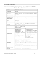
... For the latest information on supported features for the PowerEdge R710, visit Dell.com. Table 2. Product Features Summary Feature Technical Specification Form Factor Processors 2U rack Dual-core, quad-core, or six-core Intel® Xeon® processor ... to 288GB (18 DIMM slots): 1GB/2GB/4GB/8GB/16GB DDR3 800MHz, 1066MHz, or 1333MHz I/O Slots 2 PCIe x8 + 2 PCIe x4 Gen2 or 1 x16 + 2 x4 Gen2 RAID Controller Internal Controllers: PERC H200 (6Gb/s) PERC H700 (6Gb/s) (nonvolatile battery-backed cache: 512MB, 1G) SAS 6/iR PERC 6/i (battery-backed cache: 256MB) External...
... For the latest information on supported features for the PowerEdge R710, visit Dell.com. Table 2. Product Features Summary Feature Technical Specification Form Factor Processors 2U rack Dual-core, quad-core, or six-core Intel® Xeon® processor ... to 288GB (18 DIMM slots): 1GB/2GB/4GB/8GB/16GB DDR3 800MHz, 1066MHz, or 1333MHz I/O Slots 2 PCIe x8 + 2 PCIe x4 Gen2 or 1 x16 + 2 x4 Gen2 RAID Controller Internal Controllers: PERC H200 (6Gb/s) PERC H700 (6Gb/s) (nonvolatile battery-backed cache: 512MB, 1G) SAS 6/iR PERC 6/i (battery-backed cache: 256MB) External...
Technical Guide
Page 55
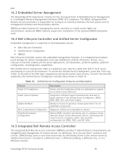
...Comprehensive Diagnostics Simplified Hardware Configuration Description Drivers and the installation utility are embedded on system Detects RAID controller and allows user to launch a separate utility. Dell Unified Server Configurator (USC) is a graphical user interface (GUI) that server is Intelligent... that aids in local server provisioning in a different country. Table 16. Dell 16.3 Embedded Server Management The PowerEdge R710 implements circuitry for all updatable components Diagnostic utilities are there‖ presence and control. PowerEdge R710 Technical Guide 55
...Comprehensive Diagnostics Simplified Hardware Configuration Description Drivers and the installation utility are embedded on system Detects RAID controller and allows user to launch a separate utility. Dell Unified Server Configurator (USC) is a graphical user interface (GUI) that server is Intelligent... that aids in local server provisioning in a different country. Table 16. Dell 16.3 Embedded Server Management The PowerEdge R710 implements circuitry for all updatable components Diagnostic utilities are there‖ presence and control. PowerEdge R710 Technical Guide 55


