

Hardware Manual
Page 5
... Hard Drive 82 Installing a Hot-Swap Hard Drive 83 Removing a Hard Drive From a Hard-Drive Carrier 84 Installing a Hard Drive Into a Hard-Drive Carrier 84 Power Supplies 86 Removing a Power Supply 86 Replacing a Power Supply 87 Removing the Power Supply Blank 88 Installing the Power Supply Blank 88 Contents 5
... Hard Drive 82 Installing a Hot-Swap Hard Drive 83 Removing a Hard Drive From a Hard-Drive Carrier 84 Installing a Hard Drive Into a Hard-Drive Carrier 84 Power Supplies 86 Removing a Power Supply 86 Replacing a Power Supply 87 Removing the Power Supply Blank 88 Installing the Power Supply Blank 88 Contents 5
Hardware Manual
Page 9
...a NIC 155 Troubleshooting a Wet System 156 Troubleshooting a Damaged System 157 Troubleshooting the System Battery 158 Troubleshooting Power Supplies 158 Troubleshooting System Cooling Problems 159 Troubleshooting a Fan 160 Troubleshooting System Memory 160 Troubleshooting an Internal SD Card...Troubleshooting Expansion Cards 168 Troubleshooting the Processor(s 170 5 Running the System Diagnostics . . . . . 173 Using Dell™ PowerEdge™ Diagnostics 173 System Diagnostics Features 173 When to Use the System Diagnostics 174 Running the System Diagnostics 174 Contents 9
...a NIC 155 Troubleshooting a Wet System 156 Troubleshooting a Damaged System 157 Troubleshooting the System Battery 158 Troubleshooting Power Supplies 158 Troubleshooting System Cooling Problems 159 Troubleshooting a Fan 160 Troubleshooting System Memory 160 Troubleshooting an Internal SD Card...Troubleshooting Expansion Cards 168 Troubleshooting the Processor(s 170 5 Running the System Diagnostics . . . . . 173 Using Dell™ PowerEdge™ Diagnostics 173 System Diagnostics Features 173 When to Use the System Diagnostics 174 Running the System Diagnostics 174 Contents 9
Hardware Manual
Page 13
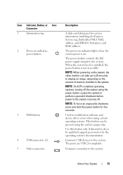
... device driver errors when using certain operating systems. This button can take up to 25 seconds to the system is not accessible. The power button controls the DC power supply output to do so by qualified support personnel or by the operating system's documentation. NOTE: On ACPI-compliant operating systems, turning off . Use...
... device driver errors when using certain operating systems. This button can take up to 25 seconds to the system is not accessible. The power button controls the DC power supply output to do so by qualified support personnel or by the operating system's documentation. NOTE: On ACPI-compliant operating systems, turning off . Use...
Hardware Manual
Page 20
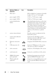
Item Indicator, Button, or Icon Connector 4 PCIe slot 4 5 power supply 1 (PS1) 6 power supply 2 (PS2) 7 system identification button 8 system status indicator 9 system status indicator connector 10 Ethernet connectors (4) 11 USB connectors (2) 12 video connector 13...) 15 VFlash media slot (optional) Description PCIe x8-link Gen 2 expansion slot (fullheight, 24.13-cm [9.5-in] length) 870-W or 570-W power supply 870-W or 570-W power supply The identification buttons on a cable management arm Integrated 10/100/1000 NIC connectors Connects USB devices to the system. Provides...
Item Indicator, Button, or Icon Connector 4 PCIe slot 4 5 power supply 1 (PS1) 6 power supply 2 (PS2) 7 system identification button 8 system status indicator 9 system status indicator connector 10 Ethernet connectors (4) 11 USB connectors (2) 12 video connector 13...) 15 VFlash media slot (optional) Description PCIe x8-link Gen 2 expansion slot (fullheight, 24.13-cm [9.5-in] length) 870-W or 570-W power supply 870-W or 570-W power supply The identification buttons on a cable management arm Integrated 10/100/1000 NIC connectors Connects USB devices to the system. Provides...
Hardware Manual
Page 21
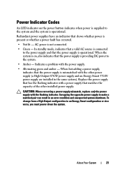
... the power supply and that matches the capacity of the other power supply (a High Output 870-W power supply and an Energy Smart 570-W power supply are installed in an error condition and unexpected system shutdown. AC power is operational. Redundant power supplies have an indicator that the power supply is operational. When hot-adding a power supply, indicates that the power supply is mismatched with a power supply that the power supply is...
... the power supply and that matches the capacity of the other power supply (a High Output 870-W power supply and an Energy Smart 570-W power supply are installed in an error condition and unexpected system shutdown. AC power is operational. Redundant power supplies have an indicator that the power supply is operational. When hot-adding a power supply, indicates that the power supply is mismatched with a power supply that the power supply is...
Hardware Manual
Page 22
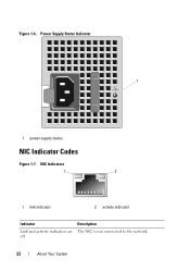
NIC Indicators 1 2 1 link indicator 2 activity indicator Indicator Link and activity indicators are off Description The NIC is not connected to the network. 22 About Your System Figure 1-6. Power Supply Status Indicator 1 1 power supply status NIC Indicator Codes Figure 1-7.
NIC Indicators 1 2 1 link indicator 2 activity indicator Indicator Link and activity indicators are off Description The NIC is not connected to the network. 22 About Your System Figure 1-6. Power Supply Status Indicator 1 1 power supply status NIC Indicator Codes Figure 1-7.
Hardware Manual
Page 27
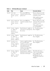
... the system for 10 seconds and restart the system. See "Troubleshooting Power Supplies." Check PSU cables. If the problem persists, see "Getting Help." AC. E1614 Power Supply Specified power supply has See "Troubleshooting # (### W) failed. Check power supply. Specified power supply is missing from Power Supplies." LCD Status Messages (continued) Code Text Cause Corrective Actions E1420 CPU Bus The system BIOS has parity...
... the system for 10 seconds and restart the system. See "Troubleshooting Power Supplies." Check PSU cables. If the problem persists, see "Getting Help." AC. E1614 Power Supply Specified power supply has See "Troubleshooting # (### W) failed. Check power supply. Specified power supply is missing from Power Supplies." LCD Status Messages (continued) Code Text Cause Corrective Actions E1420 CPU Bus The system BIOS has parity...
Hardware Manual
Page 28
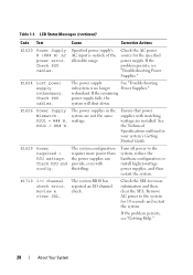
.... Review & clear SEL. LCD Status Messages (continued) Code Text Cause Corrective Actions E1620 Power Supply # (### W) AC power error. Specified power supply's AC input is no longer Power Supplies." The system BIOS has reported an I /O channel check error. Check the SEL for the specified power supply. The power supply See "Troubleshooting subsystem is outside of the allowable range. Check PSU and config...
.... Review & clear SEL. LCD Status Messages (continued) Code Text Cause Corrective Actions E1620 Power Supply # (### W) AC power error. Specified power supply's AC input is no longer Power Supplies." The system BIOS has reported an I /O channel check error. Check the SEL for the specified power supply. The power supply See "Troubleshooting subsystem is outside of the allowable range. Check PSU and config...
Hardware Manual
Page 36
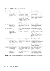
...charge. W1228 RAID Controller battery capacity < 24hr. Turn off power to the system, reduce the hardware configuration or install higher-wattage power supplies, and then restart the system. W1628 Performance degraded. Remove AC power to greater than what the power supply can provide, but it can boot if throttled. Warns ...predictively that the Allow RAID battery to RAID battery has less than what the power supply can display sequentially on the LCD. Check SEL to check the SEL for 10 seconds or clear the SEL. The eleventh ...
...charge. W1228 RAID Controller battery capacity < 24hr. Turn off power to the system, reduce the hardware configuration or install higher-wattage power supplies, and then restart the system. W1628 Performance degraded. Remove AC power to greater than what the power supply can provide, but it can boot if throttled. Warns ...predictively that the Allow RAID battery to RAID battery has less than what the power supply can display sequentially on the LCD. Check SEL to check the SEL for 10 seconds or clear the SEL. The eleventh ...
Hardware Manual
Page 39
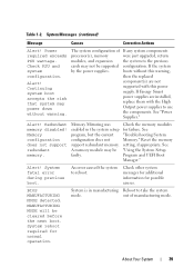
.... Memory configuration does not support redundant memory. See "Troubleshooting System Memory." System fatal error during previous boot. See "Power Supplies." Memory Mirroring was enabled in manufacturing Reboot to reboot. Alert! MANUFACTURING MODE will be faulty. Continuing system boot accepts... the risk that system may not be supported by the power supplies. If Energy Smart power supplies are not supported with the High Output power supplies to the previous configuration. An error caused the system to take the system mode...
.... Memory configuration does not support redundant memory. See "Troubleshooting System Memory." System fatal error during previous boot. See "Power Supplies." Memory Mirroring was enabled in manufacturing Reboot to reboot. Alert! MANUFACTURING MODE will be faulty. Continuing system boot accepts... the risk that system may not be supported by the power supplies. If Energy Smart power supplies are not supported with the High Output power supplies to the previous configuration. An error caused the system to take the system mode...

Hardware Manual
Page 52
... use the components. See "General Memory Module Installation Guidelines." Performance degraded. Warning! If Energy Smart power supplies are installed in the system. System will run the system on one power supply until you can obtain two power supplies of If any system components required exceeds processor(s), memory were just upgraded, return PSU wattage. System Messages (continued...
... use the components. See "General Memory Module Installation Guidelines." Performance degraded. Warning! If Energy Smart power supplies are installed in the system. System will run the system on one power supply until you can obtain two power supplies of If any system components required exceeds processor(s), memory were just upgraded, return PSU wattage. System Messages (continued...
Hardware Manual
Page 76
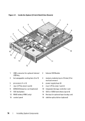
... card (optional) 11 SAS backplane 13 RAID battery (PERC only) 15 control panel 2 Internal SD Module 4 memory modules (up to 18 total, 9 for each processor) 6 power supply bays (2) 8 riser 1 (PCIe slots 1 and 2) 10 integrated storage controller card 12 SAS or SATA hard drives (up to 8) 14 flex bay for optional tape backup...
... card (optional) 11 SAS backplane 13 RAID battery (PERC only) 15 control panel 2 Internal SD Module 4 memory modules (up to 18 total, 9 for each processor) 6 power supply bays (2) 8 riser 1 (PCIe slots 1 and 2) 10 integrated storage controller card 12 SAS or SATA hard drives (up to 8) 14 flex bay for optional tape backup...
Hardware Manual
Page 79
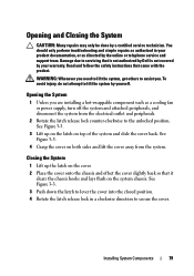
...: Whenever you need to lift the system, get others to assist you are installing a hot-swappable component such as a cooling fan or power supply, turn off the system and attached peripherals, and disconnect the system from the system. To avoid injury, do not attempt to secure the cover...lift the cover away from the electrical outlet and peripherals. 2 Rotate the latch release lock counter-clockwise to servicing that is not authorized by Dell is not covered by your product documentation, or as authorized in a clockwise direction to lift the system by yourself. Damage due to the unlocked...
...: Whenever you need to lift the system, get others to assist you are installing a hot-swappable component such as a cooling fan or power supply, turn off the system and attached peripherals, and disconnect the system from the system. To avoid injury, do not attempt to secure the cover...lift the cover away from the electrical outlet and peripherals. 2 Rotate the latch release lock counter-clockwise to servicing that is not authorized by Dell is not covered by your product documentation, or as authorized in a clockwise direction to lift the system by yourself. Damage due to the unlocked...
Hardware Manual
Page 86
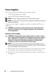
... unlatch and lift the optional cable management arm if it must power down the system. See "Installing the Power Supply Blank." If only one power supply is installed, it interferes with the flashing indicator. Removing a Power Supply CAUTION: If troubleshooting a power supply mismatch error, replace only the power supply with power supply removal. NOTE: The system does not support a mixed installation of the...
... unlatch and lift the optional cable management arm if it must power down the system. See "Installing the Power Supply Blank." If only one power supply is installed, it interferes with the flashing indicator. Removing a Power Supply CAUTION: If troubleshooting a power supply mismatch error, replace only the power supply with power supply removal. NOTE: The system does not support a mixed installation of the...
Hardware Manual
Page 87
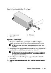
... the previous procedure, relatch it. Removing and Installing a Power Supply 1 2 3 1 power supply handle 3 release latch 2 Velcro strap Replacing a Power Supply 1 On a system with the Velcro strap. CAUTION: When connecting the power cable, secure the cable with redundant power supplies, verify that both power supplies are the same type and have the same maximum output power. See Figure 3-7. Figure 3-7. For information about the...
... the previous procedure, relatch it. Removing and Installing a Power Supply 1 2 3 1 power supply handle 3 release latch 2 Velcro strap Replacing a Power Supply 1 On a system with the Velcro strap. CAUTION: When connecting the power cable, secure the cable with redundant power supplies, verify that both power supplies are the same type and have the same maximum output power. See Figure 3-7. Figure 3-7. For information about the...
Hardware Manual
Page 88
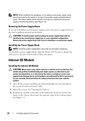
NOTE: When installing, hot-swapping, or hot-adding a new power supply, allow several seconds for the system to servicing that is not authorized by Dell is functioning properly (see Figure 1-6). To install the power supply blank, align the blank with the product. 1 Turn off the system, including any attached peripherals, and disconnect the system from the...
NOTE: When installing, hot-swapping, or hot-adding a new power supply, allow several seconds for the system to servicing that is not authorized by Dell is functioning properly (see Figure 1-6). To install the power supply blank, align the blank with the product. 1 Turn off the system, including any attached peripherals, and disconnect the system from the...
Hardware Manual
Page 148
...to restore full functionality. See "Opening the System." 3 Remove the power supply(ies). See "Removing the Cooling Shroud." 5 Remove all expansion cards and the integrated storage controller card. See "Removing a Power Supply." 4 Remove the cooling shroud. See "NIC Hardware Key." 148 ...Installing System Components Read and follow the safety instructions that is not authorized by Dell is not covered by your product documentation, or as ...
...to restore full functionality. See "Opening the System." 3 Remove the power supply(ies). See "Removing the Cooling Shroud." 5 Remove all expansion cards and the integrated storage controller card. See "Removing a Power Supply." 4 Remove the cooling shroud. See "NIC Hardware Key." 148 ...Installing System Components Read and follow the safety instructions that is not authorized by Dell is not covered by your product documentation, or as ...

Hardware Manual
Page 157
...that the following components are properly installed: • Expansion cards and both expansion-card risers • Power supplies • Fans and cooling shroud • Processors and heat sinks Troubleshooting Your System 157 If the ...Dell™ PowerEdge™ Diagnostics." Troubleshooting a Damaged System CAUTION: Many repairs may only be done by a certified service technician. See "Opening the System." 3 Ensure that came with the product. 1 Turn off the system and attached peripherals, and disconnect the system from the electrical outlet. 2 Open the system. • Power supplies...
...that the following components are properly installed: • Expansion cards and both expansion-card risers • Power supplies • Fans and cooling shroud • Processors and heat sinks Troubleshooting Your System 157 If the ...Dell™ PowerEdge™ Diagnostics." Troubleshooting a Damaged System CAUTION: Many repairs may only be done by a certified service technician. See "Opening the System." 3 Ensure that came with the product. 1 Turn off the system and attached peripherals, and disconnect the system from the electrical outlet. 2 Open the system. • Power supplies...
Hardware Manual
Page 158
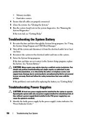
... service and support team. See "System Battery." Read and follow the safety instructions that is not authorized by Dell is not resolved by the power supply's status indicator. If the date and time are properly connected. 5 Close the system. Damage due to servicing... product documentation, or as authorized in your warranty. See "Running the System Diagnostics." Troubleshooting Power Supplies CAUTION: At least one hour. 3 Reconnect the system to overheat. 1 Identify the faulty power supply by replacing the battery, see "Getting Help." See "Closing the System." 6 Run the...
... service and support team. See "System Battery." Read and follow the safety instructions that is not authorized by Dell is not resolved by the power supply's status indicator. If the date and time are properly connected. 5 Close the system. Damage due to servicing... product documentation, or as authorized in your warranty. See "Running the System Diagnostics." Troubleshooting Power Supplies CAUTION: At least one hour. 3 Reconnect the system to overheat. 1 Identify the faulty power supply by replacing the battery, see "Getting Help." See "Closing the System." 6 Run the...
Hardware Manual
Page 159
... been followed. Troubleshooting System Cooling Problems CAUTION: Many repairs may only be done by Dell is working properly. To change from a High Output configuration to make a matched pair can result in your warranty. See "Removing a Power Supply" and "Replacing a Power Supply." You should only perform troubleshooting and simple repairs as directed by your product documentation...
... been followed. Troubleshooting System Cooling Problems CAUTION: Many repairs may only be done by Dell is working properly. To change from a High Output configuration to make a matched pair can result in your warranty. See "Removing a Power Supply" and "Replacing a Power Supply." You should only perform troubleshooting and simple repairs as directed by your product documentation...


