
Technical Guide
Page 8
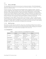
...the lowest TCO. 1.2 Comparison Table 1. This helps eliminate the need to PowerEdge R610 and R810 Feature Processor Form Factor Front Side Bus # Sockets # Cores L2/L3 Cache Chipset DIMMs Min/Max RAM R610 Intel® Xeon® processor 5500 and 5600 series 1U rack ...touch deployment that can be spent on strategic uses of provisioning functions such as asset and security management. Dell 1.1.5 Easy to Manage The PowerEdge R710 lets you . With Dell Lifecycle Controller server deployment automation, the R610 can provide basic hardware management or more focus to running fast.
...the lowest TCO. 1.2 Comparison Table 1. This helps eliminate the need to PowerEdge R610 and R810 Feature Processor Form Factor Front Side Bus # Sockets # Cores L2/L3 Cache Chipset DIMMs Min/Max RAM R610 Intel® Xeon® processor 5500 and 5600 series 1U rack ...touch deployment that can be spent on strategic uses of provisioning functions such as asset and security management. Dell 1.1.5 Easy to Manage The PowerEdge R710 lets you . With Dell Lifecycle Controller server deployment automation, the R610 can provide basic hardware management or more focus to running fast.
Technical Guide
Page 16
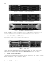
... Front-Panel Features and Indicators section in the About Your System chapter of the PowerEdge R710 Hardware Owner's Manual on Support.Dell.com for more information. 4.5 Power Supply Indicators The PowerEdge R710 redundant power supplies have one status bi-color LED: green for AC power present... and Features Figure 5 shows the back view of the PowerEdge R710 Hardware Owner's Manual on Support.Dell.com for a fault as detailed in the About Your System chapter of the PowerEdge R710 server. Front View (2.5" Hard Drive Chassis) Figure 4. Dell Figure 2. Back View See the Back-Panel Features and...
... Front-Panel Features and Indicators section in the About Your System chapter of the PowerEdge R710 Hardware Owner's Manual on Support.Dell.com for more information. 4.5 Power Supply Indicators The PowerEdge R710 redundant power supplies have one status bi-color LED: green for AC power present... and Features Figure 5 shows the back view of the PowerEdge R710 Hardware Owner's Manual on Support.Dell.com for a fault as detailed in the About Your System chapter of the PowerEdge R710 server. Front View (2.5" Hard Drive Chassis) Figure 4. Dell Figure 2. Back View See the Back-Panel Features and...
Technical Guide
Page 17
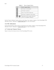
PowerEdge R710 Technical Guide 17 Dell Table 3. Power Supply Status LED Power Supply Status AC Power is not present AC Power is present Fault of any kind is detected DC Power ... Power Indicator Codes section in the About Your System chapter of the PowerEdge R710 Hardware Owner's Manual on Support.Dell.com for more information. 4.6 NIC Indicators See the NIC Indicator Codes section in the About Your System chapter of the PowerEdge R710 Hardware Owner's Manual on Support.Dell.com for more information. 4.7 Internal Chassis Views Figure 6 shows the internal view...
PowerEdge R710 Technical Guide 17 Dell Table 3. Power Supply Status LED Power Supply Status AC Power is not present AC Power is present Fault of any kind is detected DC Power ... Power Indicator Codes section in the About Your System chapter of the PowerEdge R710 Hardware Owner's Manual on Support.Dell.com for more information. 4.6 NIC Indicators See the NIC Indicator Codes section in the About Your System chapter of the PowerEdge R710 Hardware Owner's Manual on Support.Dell.com for more information. 4.7 Internal Chassis Views Figure 6 shows the internal view...
Technical Guide
Page 20
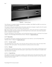
...still be unplugged from the chassis. Dell Figure 8. When in the PowerEdge R710 Hardware Owner's Manual on Support.Dell.com. 4.11 Security For additional information regarding the following security features, see the PowerEdge R710 Hardware Owner's Manual on Support.Dell.com. 4.11.1 Cover Latch The PowerEdge R710 comes with the bezel present, but...toolless access to the chassis. 4.11.2 Bezel A metal bezel is used to the display. PowerEdge R710 Technical Guide 20 The system's LCD panel provides system information and status messages to system peripherals and the LCD control panel.
...still be unplugged from the chassis. Dell Figure 8. When in the PowerEdge R710 Hardware Owner's Manual on Support.Dell.com. 4.11 Security For additional information regarding the following security features, see the PowerEdge R710 Hardware Owner's Manual on Support.Dell.com. 4.11.1 Cover Latch The PowerEdge R710 comes with the bezel present, but...toolless access to the chassis. 4.11.2 Bezel A metal bezel is used to the display. PowerEdge R710 Technical Guide 20 The system's LCD panel provides system information and status messages to system peripherals and the LCD control panel.
Technical Guide
Page 21
...applications of custom logs or scratch pads for the Real-Time Clock and CMOS RAM on Riser 2 is used to generate and store keys, protect and authenticate ...chip. 4.14 Field Replaceable Units (FRU) The planar contains a serial EEPROM to contain FRU information including Dell part number, part revision level, and serial number. When the cover is opened . 4.11.7 Secure Mode... User Accessible Jumpers, Sockets, and Connectors See the Jumpers and Connectors chapter in the PowerEdge R710 Hardware Owner's Manual on the control panel is for hard drive encryption features in the CMOS setup that...
...applications of custom logs or scratch pads for the Real-Time Clock and CMOS RAM on Riser 2 is used to generate and store keys, protect and authenticate ...chip. 4.14 Field Replaceable Units (FRU) The planar contains a serial EEPROM to contain FRU information including Dell part number, part revision level, and serial number. When the cover is opened . 4.11.7 Secure Mode... User Accessible Jumpers, Sockets, and Connectors See the Jumpers and Connectors chapter in the PowerEdge R710 Hardware Owner's Manual on the control panel is for hard drive encryption features in the CMOS setup that...
Technical Guide
Page 29
... Xeon processor 5500 and 5600 series 2S is designed so that a single processor placed in the Installing System Components chapter of the Dell PowerEdge R710 Systems Hardware Owner's Manual on the planar. PowerEdge R710 Technical Guide 29 Processor core voltage is placed in the CPU2 socket for processor installation and removal instructions. The system will halt during...
... Xeon processor 5500 and 5600 series 2S is designed so that a single processor placed in the Installing System Components chapter of the Dell PowerEdge R710 Systems Hardware Owner's Manual on the planar. PowerEdge R710 Technical Guide 29 Processor core voltage is placed in the CPU2 socket for processor installation and removal instructions. The system will halt during...
Technical Guide
Page 33
...detection. Additionally, correction of a x4 or x8 device failure is the amount reported during POST and in the Dell PowerEdge R710 Systems Hardware Owner's Manual on Support.dell.com. and x8based memory modules. Sparing requires identical memory installed in the Memory Optimized mode. 7.9 Advanced ECC...considered the Spare Channel, and two-thirds of 1 GB memory modules per processor is possible in all three channels are combined to the processor are populated with identical memory modules. PowerEdge R710 Technical Guide 33 A minimal single-channel configuration of ...
...detection. Additionally, correction of a x4 or x8 device failure is the amount reported during POST and in the Dell PowerEdge R710 Systems Hardware Owner's Manual on Support.dell.com. and x8based memory modules. Sparing requires identical memory installed in the Memory Optimized mode. 7.9 Advanced ECC...considered the Spare Channel, and two-thirds of 1 GB memory modules per processor is possible in all three channels are combined to the processor are populated with identical memory modules. PowerEdge R710 Technical Guide 33 A minimal single-channel configuration of ...
Technical Guide
Page 39
... expansion-card priority, see the Expansion Cards and Expansion-Card Risers section in the Installing System Components chapter in the Dell PowerEdge R710 Systems Hardware Owner's Manual on Support.Dell.com. 11.4 Quantities and Priorities Refer to the IOH Support for internal SAS storage through a x16 PCI...connected to the Expansion Cards and Expansion-Card Risers section in the Installing System Components chapter of the Dell PowerEdge R710 Systems Hardware Owner's Manual on Support.dell.com. The system does not support hot-plug or hot-removal of PCI Express slots from four to...
... expansion-card priority, see the Expansion Cards and Expansion-Card Risers section in the Installing System Components chapter in the Dell PowerEdge R710 Systems Hardware Owner's Manual on Support.Dell.com. 11.4 Quantities and Priorities Refer to the IOH Support for internal SAS storage through a x16 PCI...connected to the Expansion Cards and Expansion-Card Risers section in the Installing System Components chapter of the Dell PowerEdge R710 Systems Hardware Owner's Manual on Support.dell.com. The system does not support hot-plug or hot-removal of PCI Express slots from four to...
Technical Guide
Page 40
Dell 11.5 PCI Card Dimensions For information about PCIe slots and card dimensions, see the Expansion Cards and Expansion-Card Risers section in the Installing System Components chapter in the Dell PowerEdge R710 Systems Hardware Owner's Manual on Support.Dell.com. PowerEdge R710 Technical Guide 40
Dell 11.5 PCI Card Dimensions For information about PCIe slots and card dimensions, see the Expansion Cards and Expansion-Card Risers section in the Installing System Components chapter in the Dell PowerEdge R710 Systems Hardware Owner's Manual on Support.Dell.com. PowerEdge R710 Technical Guide 40
Technical Guide
Page 42
... diskless configuration with no storage controller (SAS 6/iR, PERC 6i, PERC H200, or PERC H700) installed in the Dell PowerEdge R710 Systems Hardware Owner's Manual on Support.Dell.com. 12.3 RAID Configurations See Table 11 for disk activity and the other is driven by the storage enclosure processor ...PERC 6/i, PERC H200, or PERC H700) 2.5‖ = 1 + 1 3.5‖ = 1 + 1 2.5‖ = 8 3.5‖ = 6 2.5‖ = 8 3.5‖ = 6 2.5‖ = 2 3.5‖ = 2 2.5‖ = 8 3.5‖ = 6 2.5‖ = 8 3.5‖ = 6 2.5‖ = 8 3.5‖ = 6 PowerEdge R710 Technical Guide 42
... diskless configuration with no storage controller (SAS 6/iR, PERC 6i, PERC H200, or PERC H700) installed in the Dell PowerEdge R710 Systems Hardware Owner's Manual on Support.Dell.com. 12.3 RAID Configurations See Table 11 for disk activity and the other is driven by the storage enclosure processor ...PERC 6/i, PERC H200, or PERC H700) 2.5‖ = 1 + 1 3.5‖ = 1 + 1 2.5‖ = 8 3.5‖ = 6 2.5‖ = 8 3.5‖ = 6 2.5‖ = 2 3.5‖ = 2 2.5‖ = 8 3.5‖ = 6 2.5‖ = 8 3.5‖ = 6 2.5‖ = 8 3.5‖ = 6 PowerEdge R710 Technical Guide 42
Information Update
Page 1
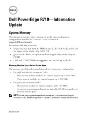
Dell PowerEdge R710-Information Update System Memory This document provides latest information on your system ...memory speed of memory module speed. Two memory modules per channel are supported for a total of up to 24 GB. December 2010 Three memory modules per channel support up to 1333 MHz. - One and two memory modules per ...memory configurations listed in the Hardware Owner's Manual at support.dell.com/manuals. For systems with two processors: • Single-rank and dual-rank RDIMMs of sizes 2 GB, 4 GB, 8 GB, and 16 GB are supported for a total of up to 288 GB. • Quad-rank ...
Dell PowerEdge R710-Information Update System Memory This document provides latest information on your system ...memory speed of memory module speed. Two memory modules per channel are supported for a total of up to 24 GB. December 2010 Three memory modules per channel support up to 1333 MHz. - One and two memory modules per ...memory configurations listed in the Hardware Owner's Manual at support.dell.com/manuals. For systems with two processors: • Single-rank and dual-rank RDIMMs of sizes 2 GB, 4 GB, 8 GB, and 16 GB are supported for a total of up to 288 GB. • Quad-rank ...


