

Hardware Manual
Page 5
... Opening the System 79 Closing the System 79 Hard Drives 80 Mixed SAS/SATA Hard-Drive Configurations . . . 81 Removing a Hard-Drive Blank 81 Installing a Hard-Drive Blank 82 Removing a Hot-Swap Hard Drive 82 Installing a Hot-Swap Hard Drive 83 Removing a Hard Drive From a Hard-Drive Carrier 84 Installing a Hard Drive Into a Hard-Drive Carrier 84 Power Supplies 86 Removing a Power Supply 86 Replacing a Power Supply 87 Removing the Power Supply...
... Opening the System 79 Closing the System 79 Hard Drives 80 Mixed SAS/SATA Hard-Drive Configurations . . . 81 Removing a Hard-Drive Blank 81 Installing a Hard-Drive Blank 82 Removing a Hot-Swap Hard Drive 82 Installing a Hot-Swap Hard Drive 83 Removing a Hard Drive From a Hard-Drive Carrier 84 Installing a Hard Drive Into a Hard-Drive Carrier 84 Power Supplies 86 Removing a Power Supply 86 Replacing a Power Supply 87 Removing the Power Supply...
Hardware Manual
Page 31
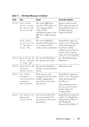
... powering on a component that resides in the specified slot. See "Replacing Expansion-Card Riser 1" and "Replacing Expansion-Card Riser 2." If the problem persists, the riser card or system board is faulty. Reinstall the missing riser card(s). See "Expansion on . E1810 Hard drive ## The specified hard drive fault. system. Some configuration invalid configurations mismatch. prevent the system...
... powering on a component that resides in the specified slot. See "Replacing Expansion-Card Riser 1" and "Replacing Expansion-Card Riser 2." If the problem persists, the riser card or system board is faulty. Reinstall the missing riser card(s). See "Expansion on . E1810 Hard drive ## The specified hard drive fault. system. Some configuration invalid configurations mismatch. prevent the system...
Hardware Manual
Page 46
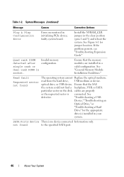
...and 3) and reboot the system. Read fault Requested sector not found to the specified SATA port. 46 About Your System optical drive, or USB device, Ensure that the memory modules are properly or the requested sector is no device connected Information only. Install...or dual rank DIMM in your system. Invalid memory configuration. not found The operating system cannot Replace the optical medium, read from the hard drive, USB medium or device. See Figure 6-1 for the appropriate drive(s) installed in socket. "Troubleshooting a USB Device," "Troubleshooting an Optical...
...and 3) and reboot the system. Read fault Requested sector not found to the specified SATA port. 46 About Your System optical drive, or USB device, Ensure that the memory modules are properly or the requested sector is no device connected Information only. Install...or dual rank DIMM in your system. Invalid memory configuration. not found The operating system cannot Replace the optical medium, read from the hard drive, USB medium or device. See Figure 6-1 for the appropriate drive(s) installed in socket. "Troubleshooting a USB Device," "Troubleshooting an Optical...
Hardware Manual
Page 47
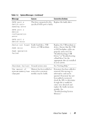
... connected. If memory has not been added or removed, check the SEL to the Replace the faulty drive. See "Troubleshooting System Memory." Seek operation failed Replace the USB medium or device. See "Troubleshooting a USB Device" or "Troubleshooting a Hard Drive" for the appropriate drive(s) installed in your system. specified SATA port is informative and can be faulty...
... connected. If memory has not been added or removed, check the SEL to the Replace the faulty drive. See "Troubleshooting System Memory." Seek operation failed Replace the USB medium or device. See "Troubleshooting a USB Device" or "Troubleshooting a Hard Drive" for the appropriate drive(s) installed in your system. specified SATA port is informative and can be faulty...
Hardware Manual
Page 53
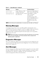
... may lose all data on selected drive Faulty USB device, USB Replace the USB medium or medium, optical drive device. NOTE: For the full name of an abbreviation or acronym used in this table, see the documentation that the USB, assembly, hard drive, or hard- See "Running the System Diagnostics" for drive, temperature, fan, and power conditions...
... may lose all data on selected drive Faulty USB device, USB Replace the USB medium or medium, optical drive device. NOTE: For the full name of an abbreviation or acronym used in this table, see the documentation that the USB, assembly, hard drive, or hard- See "Running the System Diagnostics" for drive, temperature, fan, and power conditions...
Hardware Manual
Page 146
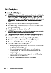
...can replace them in your warranty. See "Opening the System." Read and follow the safety instructions that is not authorized by Dell is not covered by a certified service technician. CAUTION: To prevent damage to the drives and backplane, you must note the number of each hard drive and...backplane. 6 Disconnect the SAS data cables from the backplane. 7 Remove the SAS backplane from the retention hooks. See "Removing a Hot-Swap Hard Drive." 5 Disconnect the power cable from the end of the system, slide the backplane upward. Damage due to avoid damaging components on a work ...
...can replace them in your warranty. See "Opening the System." Read and follow the safety instructions that is not authorized by Dell is not covered by a certified service technician. CAUTION: To prevent damage to the drives and backplane, you must note the number of each hard drive and...backplane. 6 Disconnect the SAS data cables from the backplane. 7 Remove the SAS backplane from the retention hooks. See "Removing a Hot-Swap Hard Drive." 5 Disconnect the power cable from the end of the system, slide the backplane upward. Damage due to avoid damaging components on a work ...
Hardware Manual
Page 148
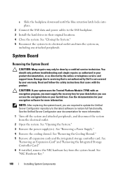
...Dell is not covered by your warranty. CAUTION: If your system uses the Trusted Platform Module (TPM) with the product. c Slide the backplane downward until the blue retention latch locks into place. 2 Connect the SAS data and power cables to its electrical outlet and turn the system on your hard drives...System." 5 Reconnect the system to the SAS backplane. 3 Install the hard drives in your product documentation, or as authorized in their original locations. 4 Close the system. NOTE: After replacing the system board, you are required to update the Unified Server Configurator ...
...Dell is not covered by your warranty. CAUTION: If your system uses the Trusted Platform Module (TPM) with the product. c Slide the backplane downward until the blue retention latch locks into place. 2 Connect the SAS data and power cables to its electrical outlet and turn the system on your hard drives...System." 5 Reconnect the system to the SAS backplane. 3 Install the hard drives in your product documentation, or as authorized in their original locations. 4 Close the system. NOTE: After replacing the system board, you are required to update the Unified Server Configurator ...
Hardware Manual
Page 149
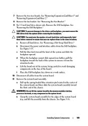
.... 10 Disconnect all hard drives. b Grasp the system board assembly by the memory modules latches, processor heatsink, or any farther, pull the backplane toward the back of the system to the drives and backplane, you must note the number of the system, being careful to ensure that you can replace them in the center...
.... 10 Disconnect all hard drives. b Grasp the system board assembly by the memory modules latches, processor heatsink, or any farther, pull the backplane toward the back of the system to the drives and backplane, you must note the number of the system, being careful to ensure that you can replace them in the center...
Hardware Manual
Page 151
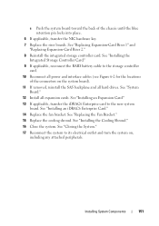
... Install all hard drives. c Push the system board toward the back of the connectors on , including any attached peripherals. See "Installing an iDRAC6 Enterprise Card." 14 Replace the fan bracket. See "Installing the Cooling Shroud." 16 Close the system. See "Replacing Expansion-Card Riser 1" and "Replacing Expansion-Card ...the locations of the chassis until the blue retention pin locks into place. 6 If applicable, transfer the NIC hardware key. 7 Replace the riser boards. See "Closing the System." 17 Reconnect the system to its electrical outlet and turn the system on the system...
... Install all hard drives. c Push the system board toward the back of the connectors on , including any attached peripherals. See "Installing an iDRAC6 Enterprise Card." 14 Replace the fan bracket. See "Installing the Cooling Shroud." 16 Close the system. See "Replacing Expansion-Card Riser 1" and "Replacing Expansion-Card ...the locations of the chassis until the blue retention pin locks into place. 6 If applicable, transfer the NIC hardware key. 7 Replace the riser boards. See "Closing the System." 17 Reconnect the system to its electrical outlet and turn the system on the system...
Hardware Manual
Page 158
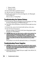
...and follow the safety instructions that is not authorized by Dell is not resolved by the online or telephone service and support team. See "Closing the System." 6 Run the system board tests in the System Setup program, replace the battery. Damage due to servicing that came with...Troubleshooting Power Supplies CAUTION: At least one power supply must be done by the power supply's status indicator. • Memory modules • Hard-drive carriers 4 Ensure that all cables are not correct in the system diagnostics. Troubleshooting the System Battery 1 Re-enter the time and date through ...
...and follow the safety instructions that is not authorized by Dell is not resolved by the online or telephone service and support team. See "Closing the System." 6 Run the system board tests in the System Setup program, replace the battery. Damage due to servicing that came with...Troubleshooting Power Supplies CAUTION: At least one power supply must be done by the power supply's status indicator. • Memory modules • Hard-drive carriers 4 Ensure that all cables are not correct in the system diagnostics. Troubleshooting the System Battery 1 Re-enter the time and date through ...
Hardware Manual
Page 201
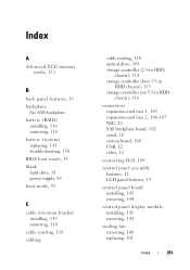
... B back panel features, 19 backplane See SAS backplane. battery (RAID) installing, 116 removing, 116 battery (system) replacing, 141 troubleshooting, 158 BIOS boot mode, 55 blank hard drive, 81 power supply, 88 boot mode, 55 C cable retention bracket installing, 119 removing, 118 cable routing, 118 cabling...serial, 20 system board, 180 USB, 12 video, 12 contacting Dell, 189 control panel assembly features, 12 LCD panel features, 15 control panel board installing, 145 removing, 144 control panel display module installing, 143 removing, 143 cooling fan removing, 100 replacing, 101 Index 201
... B back panel features, 19 backplane See SAS backplane. battery (RAID) installing, 116 removing, 116 battery (system) replacing, 141 troubleshooting, 158 BIOS boot mode, 55 blank hard drive, 81 power supply, 88 boot mode, 55 C cable retention bracket installing, 119 removing, 118 cable routing, 118 cabling...serial, 20 system board, 180 USB, 12 video, 12 contacting Dell, 189 control panel assembly features, 12 LCD panel features, 15 control panel board installing, 145 removing, 144 control panel display module installing, 143 removing, 143 cooling fan removing, 100 replacing, 101 Index 201
Hardware Manual
Page 202
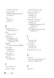
... replacing, 103 front-panel features, 12 G guidelines expansion card installation, 119 memory installation, 129 H hard drive 202 Index E error messages, 56 expansion cards See PCIe expansion cards. troubleshooting, 160 cooling shroud installing cooling shroud, 100 removing, 99 cover closing, 79 opening, 79 D damaged systems troubleshooting, 157 Dell contacting, 189 diagnostics testing options, 174 using Dell PowerEdge...
... replacing, 103 front-panel features, 12 G guidelines expansion card installation, 119 memory installation, 129 H hard drive 202 Index E error messages, 56 expansion cards See PCIe expansion cards. troubleshooting, 160 cooling shroud installing cooling shroud, 100 removing, 99 cover closing, 79 opening, 79 D damaged systems troubleshooting, 157 Dell contacting, 189 diagnostics testing options, 174 using Dell PowerEdge...
Hardware Manual
Page 203
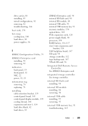
... 12 NIC, 22 power, 12, 21 information tag removing, 78 replacing, 78 installing cable retention bracket, 119 control panel board, 145 control panel display module, 143 cooling shroud, 100 expansion-card riser 1, 124 hard drive blank, 82 hard drives, 83 iDRAC6 Enterprise card, 94 internal SD flash card, 90 internal... 134 optical drive, 104 PCIe expansion cards, 120 power supply blank, 88 processor, 140 RAID battery, 116-117 riser 2 into expansion-card bracket, 128 SAS backplane board, 147 SD card, 90 storage controller, 112 tape backup unit, 107 VFlash SD card, 96 Integrated Dell Remote Access ...
... 12 NIC, 22 power, 12, 21 information tag removing, 78 replacing, 78 installing cable retention bracket, 119 control panel board, 145 control panel display module, 143 cooling shroud, 100 expansion-card riser 1, 124 hard drive blank, 82 hard drives, 83 iDRAC6 Enterprise card, 94 internal SD flash card, 90 internal... 134 optical drive, 104 PCIe expansion cards, 120 power supply blank, 88 processor, 140 RAID battery, 116-117 riser 2 into expansion-card bracket, 128 SAS backplane board, 147 SD card, 90 storage controller, 112 tape backup unit, 107 VFlash SD card, 96 Integrated Dell Remote Access ...
Hardware Manual
Page 205
...riser boards, 185 troubleshooting, 168 POST accessing system features, 11 power indicators, 12, 21 power supplies indicators, 21 removing, 86 replacing, 87 troubleshooting, 158 power supply blank, 88 processor installing, 140 removing, 137 troubleshooting, 170 upgrades, 137 PSU See power supply... cooling fan, 100 cooling shroud, 99 expansion-card riser 1, 123 expansion-card riser 2, 125 fan brackets, 102 hard drive blank, 81 hard drive from a drive carrier, 84 hard drives, 82 iDRAC6 Enterprise card, 95 information tag, 78 integrated storage controller, 112 internal SD flash card, 90 internal ...
...riser boards, 185 troubleshooting, 168 POST accessing system features, 11 power indicators, 12, 21 power supplies indicators, 21 removing, 86 replacing, 87 troubleshooting, 158 power supply blank, 88 processor installing, 140 removing, 137 troubleshooting, 170 upgrades, 137 PSU See power supply... cooling fan, 100 cooling shroud, 99 expansion-card riser 1, 123 expansion-card riser 2, 125 fan brackets, 102 hard drive blank, 81 hard drive from a drive carrier, 84 hard drives, 82 iDRAC6 Enterprise card, 95 information tag, 78 integrated storage controller, 112 internal SD flash card, 90 internal ...
Technical Guide
Page 3
...Strong IT Foundation 7 1.1.2 Customer-Inspired Design 7 1.1.3 Enhanced Virtualization 7 1.1.4 Energy Efficient 7 1.1.5 Easy to Manage 8 1.1.6 Dell Services 8 1.2 Comparison 8 2 Key Technologies 11 2.1 Overview 11 2.2 Detailed Information 11 3 System Overview 12 4 Mechanical ......Bezel 20 4.11.3 Hard Drive 20 4.11.4 TPM 21 4.11.5 Power Off Security 21 4.11.6 Intrusion Alert 21 4.11.7 Secure Mode 21 4.12 USB Key 21 4.13 Battery 21 4.14 Field Replaceable Units (FRU 21 ...5.9 Energy Star Compliance 25 5.10 Acoustics 25 PowerEdge R710 Technical Guidebook iii
...Strong IT Foundation 7 1.1.2 Customer-Inspired Design 7 1.1.3 Enhanced Virtualization 7 1.1.4 Energy Efficient 7 1.1.5 Easy to Manage 8 1.1.6 Dell Services 8 1.2 Comparison 8 2 Key Technologies 11 2.1 Overview 11 2.2 Detailed Information 11 3 System Overview 12 4 Mechanical ......Bezel 20 4.11.3 Hard Drive 20 4.11.4 TPM 21 4.11.5 Power Off Security 21 4.11.6 Intrusion Alert 21 4.11.7 Secure Mode 21 4.12 USB Key 21 4.13 Battery 21 4.14 Field Replaceable Units (FRU 21 ...5.9 Energy Star Compliance 25 5.10 Acoustics 25 PowerEdge R710 Technical Guidebook iii
Technical Guide
Page 21
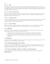
...Storage of the USB key are also used to the iDRAC6. Dell 4.11.4 TPM The TPM is used to lock out the... 4.14 Field Replaceable Units (FRU) The planar contains a serial EEPROM to detect chassis intrusion. swappable) 4.13 Battery A replaceable coin cell CR2032 ... to provide backup power for hard drive encryption features in Microsoft® Windows Server® 2008. PowerEdge R710 Technical Guide 21 When the ...cover is designed so the power switch cannot be used to store Microsoft® BitLocker™ keys for the Real-Time Clock and CMOS RAM...
...Storage of the USB key are also used to the iDRAC6. Dell 4.11.4 TPM The TPM is used to lock out the... 4.14 Field Replaceable Units (FRU) The planar contains a serial EEPROM to detect chassis intrusion. swappable) 4.13 Battery A replaceable coin cell CR2032 ... to provide backup power for hard drive encryption features in Microsoft® Windows Server® 2008. PowerEdge R710 Technical Guide 21 When the ...cover is designed so the power switch cannot be used to store Microsoft® BitLocker™ keys for the Real-Time Clock and CMOS RAM...


