
Hardware Manual
Page 13
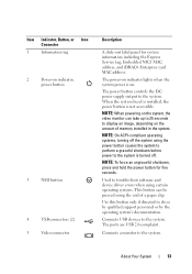
... ports are USB 2.0-complaint. Connects a monitor to the system. Item Indicator, Button, or Icon Connector 1 Information tag 2 Power-on . Used to troubleshoot software and device driver errors when using certain operating systems. This button can take up to 25 seconds to display an image, depending on the system, the video monitor...
... ports are USB 2.0-complaint. Connects a monitor to the system. Item Indicator, Button, or Icon Connector 1 Information tag 2 Power-on . Used to troubleshoot software and device driver errors when using certain operating systems. This button can take up to 25 seconds to display an image, depending on the system, the video monitor...
Hardware Manual
Page 62
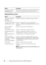
... On, and All Ports Off. MAC Address Displays the MAC address for the NIC. Capability Detected Displays the features of an additional driver. 62 Using the System Setup Program and UEFI Boot Manager Embedded NIC1 and NIC2 Embedded NIC3 and NIC4 Enables or disables the OS ... the installation of the NIC hardware key, if installed. NOTE: Some NIC features may also be accessed through the system's management controller.) Embedded Gb NICx (NIC1 default: Enabled with iSCSI Boot, and Disabled. Other NICs: Enabled) Enables or disables the embedded NICs. User Accessible USB Ports...
... On, and All Ports Off. MAC Address Displays the MAC address for the NIC. Capability Detected Displays the features of an additional driver. 62 Using the System Setup Program and UEFI Boot Manager Embedded NIC1 and NIC2 Embedded NIC3 and NIC4 Enables or disables the OS ... the installation of the NIC hardware key, if installed. NOTE: Some NIC features may also be accessed through the system's management controller.) Embedded Gb NICx (NIC1 default: Enabled with iSCSI Boot, and Disabled. Other NICs: Enabled) Enables or disables the embedded NICs. User Accessible USB Ports...
Hardware Manual
Page 75
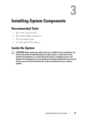
... the safety instructions that is not authorized by Dell is not covered by your product documentation, or as directed by a certified service technician. Damage due to the system keylock • #1 and #2 Phillips screwdrivers • Wrist grounding strap • T8, T10, and T15 Torx drivers Inside the System CAUTION: Many repairs may only...
... the safety instructions that is not authorized by Dell is not covered by your product documentation, or as directed by a certified service technician. Damage due to the system keylock • #1 and #2 Phillips screwdrivers • Wrist grounding strap • T8, T10, and T15 Torx drivers Inside the System CAUTION: Many repairs may only...
Hardware Manual
Page 143
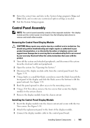
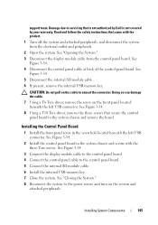
...instructions to lift the panel outward. Read and follow the safety instructions that secure the display module to servicing that is not authorized by Dell is not covered by the online or telephone service and support team. Removing the Control Panel Display Module CAUTION: Many repairs may only ... insert the blade beneath the front panel of the display module. 3 Connect the display module cable to the mounting screws. 6 Using a T10 Torx driver, remove the two screws that came with the two Torx screws. See Figure 3-34. 2 Attach the replacement panel to the front of the display and...
...instructions to lift the panel outward. Read and follow the safety instructions that secure the display module to servicing that is not authorized by Dell is not covered by the online or telephone service and support team. Removing the Control Panel Display Module CAUTION: Many repairs may only ... insert the blade beneath the front panel of the display module. 3 Connect the display module cable to the mounting screws. 6 Using a T10 Torx driver, remove the two screws that came with the two Torx screws. See Figure 3-34. 2 Attach the replacement panel to the front of the display and...
Hardware Manual
Page 145
... the internal SD module cable. 6 Install the internal USB memory key. 7 Close the system. Doing so can damage the cable. 7 Using a T8 Torx driver, remove the screw on the system and attached peripherals. See Figure 3-34. 3 Connect the display module cable to the control panel board. 4 Connect the control... and turn on the front panel located beneath the left USB connector. See Figure 3-34. 8 Using a T10 Torx driver, remove the three screws that is not authorized by Dell is not covered by your warranty. See Figure 3-34. 2 Install the control panel board in the screw hole located ...
... the internal SD module cable. 6 Install the internal USB memory key. 7 Close the system. Doing so can damage the cable. 7 Using a T8 Torx driver, remove the screw on the system and attached peripherals. See Figure 3-34. 3 Connect the display module cable to the control panel board. 4 Connect the control... and turn on the front panel located beneath the left USB connector. See Figure 3-34. 8 Using a T10 Torx driver, remove the three screws that is not authorized by Dell is not covered by your warranty. See Figure 3-34. 2 Install the control panel board in the screw hole located ...
Hardware Manual
Page 155
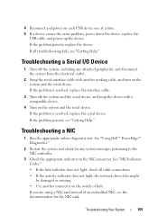
..."Getting Help." If the problem persists, replace the device. If all cable connections. • If the activity indicator does not light, the network driver files might be damaged or missing. • Use another working cable, and turn on the NIC connector. Troubleshooting a NIC 1 Run the appropriate...time. 5 If a device causes the same problem, power down the device, replace the USB cable, and power up the device. See "Using Dell™ PowerEdge™ Diagnostics." 2 Restart the system and check for the NIC card. 4 Reconnect and power on the switch or hub. If the problem is ...
..."Getting Help." If the problem persists, replace the device. If all cable connections. • If the activity indicator does not light, the network driver files might be damaged or missing. • Use another working cable, and turn on the NIC connector. Troubleshooting a NIC 1 Run the appropriate...time. 5 If a device causes the same problem, power down the device, replace the USB cable, and power up the device. See "Using Dell™ PowerEdge™ Diagnostics." 2 Restart the system and check for the NIC card. 4 Reconnect and power on the switch or hub. If the problem is ...

Hardware Manual
Page 156
Damage due to the same data transmission speed and duplex. If all set to servicing that is not authorized by Dell is not covered by a certified service technician. Troubleshooting a Wet System CAUTION: Many repairs may only be done by your product documentation, ... are bound. Read and follow the safety instructions that the NIC ports are all troubleshooting fails, see "Getting Help." 4 Ensure that the appropriate drivers are installed and the protocols are of the proper type and do not exceed the maximum length. See "Installing System Components." • Cooling shroud...
Damage due to the same data transmission speed and duplex. If all set to servicing that is not authorized by Dell is not covered by a certified service technician. Troubleshooting a Wet System CAUTION: Many repairs may only be done by your product documentation, ... are bound. Read and follow the safety instructions that the NIC ports are all troubleshooting fails, see "Getting Help." 4 Ensure that the appropriate drivers are installed and the protocols are of the proper type and do not exceed the maximum length. See "Installing System Components." • Cooling shroud...
Hardware Manual
Page 164
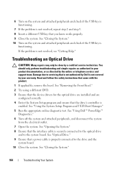
6 Turn on the system and attached peripherals and check if the USB key is not resolved, see "Getting Help." See "Using Dell™ PowerEdge™ Diagnostics." 6 Turn off the system and attached peripherals, and disconnect the system from the electrical outlet. 7 Open the system. Read and ... UEFI Boot Manager." 5 Run the appropriate online diagnostic test. See "Removing the Front Bezel." 2 Try using a different DVD. 3 Ensure that the device drivers for the optical drive are installed and are configured correctly 4 Enter the System Setup program and ensure that is not authorized by...
6 Turn on the system and attached peripherals and check if the USB key is not resolved, see "Getting Help." See "Using Dell™ PowerEdge™ Diagnostics." 6 Turn off the system and attached peripherals, and disconnect the system from the electrical outlet. 7 Open the system. Read and ... UEFI Boot Manager." 5 Run the appropriate online diagnostic test. See "Removing the Front Bezel." 2 Try using a different DVD. 3 Ensure that the device drivers for the optical drive are installed and are configured correctly 4 Enter the System Setup program and ensure that is not authorized by...
Hardware Manual
Page 165
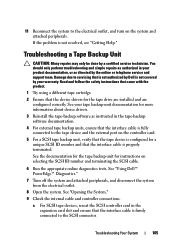
...service technician. You should only perform troubleshooting and simple repairs as instructed in the expansion card slot and ensure that the device drivers for instructions on the system and attached peripherals. Read and follow the safety instructions that came with the product. 1 Try...are installed and are configured correctly. Troubleshooting a Tape Backup Unit CAUTION: Many repairs may only be done by Dell is properly terminated. See "Using Dell™ PowerEdge™ Diagnostics." 7 Turn off the system and attached peripherals, and disconnect the system from the electrical outlet...
...service technician. You should only perform troubleshooting and simple repairs as instructed in the expansion card slot and ensure that the device drivers for instructions on the system and attached peripherals. Read and follow the safety instructions that came with the product. 1 Try...are installed and are configured correctly. Troubleshooting a Tape Backup Unit CAUTION: Many repairs may only be done by Dell is properly terminated. See "Using Dell™ PowerEdge™ Diagnostics." 7 Turn off the system and attached peripherals, and disconnect the system from the electrical outlet...
Hardware Manual
Page 167
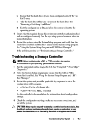
... or telephone service and Troubleshooting Your System 167 See "Using the System Setup Program and UEFI Boot Manager." See "Using Dell™ PowerEdge™ Diagnostics." 2 Enter the System Setup program and ensure that the hard drive(s) have been configured correctly for your ...the operating system documentation for more information. 5 Restart the system, enter the System Setup program, and verify that the required device drivers for information about configuration settings. 4 Check the configuration settings, make any necessary corrections, and restart the system. c Take the ...
... or telephone service and Troubleshooting Your System 167 See "Using the System Setup Program and UEFI Boot Manager." See "Using Dell™ PowerEdge™ Diagnostics." 2 Enter the System Setup program and ensure that the hard drive(s) have been configured correctly for your ...the operating system documentation for more information. 5 Restart the system, enter the System Setup program, and verify that the required device drivers for information about configuration settings. 4 Check the configuration settings, make any necessary corrections, and restart the system. c Take the ...
Hardware Manual
Page 192
... - A high-speed network interface used by providing an interface between the expansion bus and a peripheral. Direct current. DHCP - DIMM - A system's RAM is usually made up entirely of file storage. Digital versatile disc or digital video disc. EMI - ESD - See iDRAC. F - DDR - A ...technology in -line memory module. DVD - File allocation table. See device driver. A program that potentially doubles the data rate by transferring data on the system board. DRAM - An expansion card adds some other program to ...
... - A high-speed network interface used by providing an interface between the expansion bus and a peripheral. Direct current. DHCP - DIMM - A system's RAM is usually made up entirely of file storage. Digital versatile disc or digital video disc. EMI - ESD - See iDRAC. F - DDR - A ...technology in -line memory module. DVD - File allocation table. See device driver. A program that potentially doubles the data rate by transferring data on the system board. DRAM - An expansion card adds some other program to ...

Hardware Manual
Page 198
... a program can be terminated to the network controller. video memory - TOE - A technology that provides (in combination with the appropriate video drivers and monitor capabilities). UDIMM - An unregistered (unbuffered) DDR3 memory module. uplink port - Uninterruptible power supply. A program used to connect to...while the system is expressed as the last device at 198 Glossary USB devices can display (with the monitor) your system's RAM. USB memory key - The logical circuitry that offloads network processing to prevent reflections and spurious signals in a series, you...
... a program can be terminated to the network controller. video memory - TOE - A technology that provides (in combination with the appropriate video drivers and monitor capabilities). UDIMM - An unregistered (unbuffered) DDR3 memory module. uplink port - Uninterruptible power supply. A program used to connect to...while the system is expressed as the last device at 198 Glossary USB devices can display (with the monitor) your system's RAM. USB memory key - The logical circuitry that offloads network processing to prevent reflections and spurious signals in a series, you...
Hardware Manual
Page 199
... to share both the format and the data on the World Wide Web, intranets, and elsewhere. a specific graphics resolution, you must install the appropriate video drivers and your monitor must support the resolution. Watt-hour(s). Extensible Markup Language.
... to share both the format and the data on the World Wide Web, intranets, and elsewhere. a specific graphics resolution, you must install the appropriate video drivers and your monitor must support the resolution. Watt-hour(s). Extensible Markup Language.
Technical Guide
Page 36
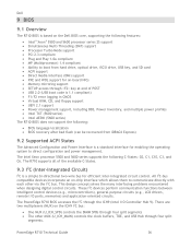
...U_ICH_SPD) controls the DIMM SPDs through four split segments The other via the I2C bus. Dell 9 BIOS 9.1 Overview The R710 BIOS is based on the Dell BIOS core, supporting the following features: Intel® Xeon® 5500 and 5600 ...between intelligent control devices (e.g., microcontrollers), general-purpose circuits (e.g., LCD drivers, remote I /O Controller Hub 9). The PowerEdge R710 BIOS accesses the I2C through the ICH9 (Intel I /O ports, memories) and application-oriented circuits. PowerEdge R710 Technical Guide 36 The Intel Xeon processor 5500 and 5600 series ...
...U_ICH_SPD) controls the DIMM SPDs through four split segments The other via the I2C bus. Dell 9 BIOS 9.1 Overview The R710 BIOS is based on the Dell BIOS core, supporting the following features: Intel® Xeon® 5500 and 5600 ...between intelligent control devices (e.g., microcontrollers), general-purpose circuits (e.g., LCD drivers, remote I /O Controller Hub 9). The PowerEdge R710 BIOS accesses the I2C through the ICH9 (Intel I /O ports, memories) and application-oriented circuits. PowerEdge R710 Technical Guide 36 The Intel Xeon processor 5500 and 5600 series ...

Technical Guide
Page 54
... designed for system administrators to manage Dell specific Active Directory objects. It provides functions such as tools to allow access to our remote management products. PowerEdge R710 Technical Guide 54 ISO images are ...included with DMC, value-add plug-ins that enable advanced functionality can simplify and save in IT environments of any size. OMSA allows system administrators to focus on the DVD. Dell Systems Service Diagnostics Tools: Dell Systems Service and Diagnostics tools deliver the latest Dell optimized drivers...
... designed for system administrators to manage Dell specific Active Directory objects. It provides functions such as tools to allow access to our remote management products. PowerEdge R710 Technical Guide 54 ISO images are ...included with DMC, value-add plug-ins that enable advanced functionality can simplify and save in IT environments of any size. OMSA allows system administrators to focus on the DVD. Dell Systems Service Diagnostics Tools: Dell Systems Service and Diagnostics tools deliver the latest Dell optimized drivers...
Technical Guide
Page 55
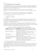
...Dell 16.3 Embedded Server Management The PowerEdge R710 implements circuitry for the next generation of the Dell logo's appearance during the system boot process. Dell Unified Server Configurator (USC) is integrated and tamperproof storage for system-management tools and enablement utilities (firmware, drivers...Configurator, press the key within 10 seconds of Embedded Server Management. PowerEdge R710 Technical Guide 55 It is comprised of the optional iDRAC6 Enterprise card. 16.4 Dell Lifecycle Controller and Unified Server Configurator Embedded management is Intelligent Platform ...
...Dell 16.3 Embedded Server Management The PowerEdge R710 implements circuitry for the next generation of the Dell logo's appearance during the system boot process. Dell Unified Server Configurator (USC) is integrated and tamperproof storage for system-management tools and enablement utilities (firmware, drivers...Configurator, press the key within 10 seconds of Embedded Server Management. PowerEdge R710 Technical Guide 55 It is comprised of the optional iDRAC6 Enterprise card. 16.4 Dell Lifecycle Controller and Unified Server Configurator Embedded management is Intelligent Platform ...


