Owners Manual
Page 21
.... • Not lit - Indicates a problem with the flashing indicator. Power Indicator Codes An LED indicator on , it also indicates that the power supply is mismatched with the other installed power supply. The power supplies have an indicator that the power supply is operational. CAUTION: If troubleshooting a PSU mismatch error, replace only the power supply with the power supply. • Alternating green and amber - To change from a High Output configuration to the system and the...
.... • Not lit - Indicates a problem with the flashing indicator. Power Indicator Codes An LED indicator on , it also indicates that the power supply is mismatched with the other installed power supply. The power supplies have an indicator that the power supply is operational. CAUTION: If troubleshooting a PSU mismatch error, replace only the power supply with the power supply. • Alternating green and amber - To change from a High Output configuration to the system and the...
Owners Manual
Page 43
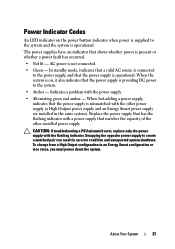
... system board Keyboard data line failure Keyboard stuck key failure Keyboard cable connector is improperly connected or the keyboard is in a valid configuration. If the problem persists, see "Troubleshooting a USB Device." Manufacturing mode detected System is defective. The system will run but with the specified DIMM disabled. See "Integrated Storage Controller Card." Reseat the keyboard cable. Local keyboard may not work All USB ports are installed in manufacturing Reboot to change settings. Ensure that the memory modules are disabled, preventing keyboard access...
... system board Keyboard data line failure Keyboard stuck key failure Keyboard cable connector is improperly connected or the keyboard is in a valid configuration. If the problem persists, see "Troubleshooting a USB Device." Manufacturing mode detected System is defective. The system will run but with the specified DIMM disabled. See "Integrated Storage Controller Card." Reseat the keyboard cable. Local keyboard may not work All USB ports are installed in manufacturing Reboot to change settings. Ensure that the memory modules are disabled, preventing keyboard access...

Owners Manual
Page 47
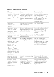
... drive subsystem. SATA port x There is faulty. SATA port x device configuration error SATA port x device error Sector not found Faulty USB device, USB Replace the USB medium or medium, optical drive device. See "Troubleshooting a USB Device" or "Troubleshooting Hard Drives" for the appropriate drive(s) installed in your system. Seek operation failed Replace the USB medium or device. Table 1-2. See "Troubleshooting a USB Device," "Troubleshooting an Internal SD Card," and "Troubleshooting Hard Drives." SATA port x device autosensing error The drive connected...
... drive subsystem. SATA port x There is faulty. SATA port x device configuration error SATA port x device error Sector not found Faulty USB device, USB Replace the USB medium or medium, optical drive device. See "Troubleshooting a USB Device" or "Troubleshooting Hard Drives" for the appropriate drive(s) installed in your system. Seek operation failed Replace the USB medium or device. Table 1-2. See "Troubleshooting a USB Device," "Troubleshooting an Internal SD Card," and "Troubleshooting Hard Drives." SATA port x device autosensing error The drive connected...
Owners Manual
Page 53
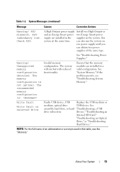
... run the system on selected drive Faulty USB device, USB Replace the USB medium or medium, optical drive USB device. NOTE: For the full name of the same type. PSU mismatch. You system at the same time. "Troubleshooting a USB drive subsystem. If the problem persists, see the "Glossary." The recommended memory configuration is not optimal. Table 1-2. Check PSU. See "System Memory." See "Troubleshooting Power Supplies." Ensure that the memory modules are installed in the supplies...
... run the system on selected drive Faulty USB device, USB Replace the USB medium or medium, optical drive USB device. NOTE: For the full name of the same type. PSU mismatch. You system at the same time. "Troubleshooting a USB drive subsystem. If the problem persists, see the "Glossary." The recommended memory configuration is not optimal. Table 1-2. Check PSU. See "System Memory." See "Troubleshooting Power Supplies." Ensure that the memory modules are installed in the supplies...

Owners Manual
Page 57
... enables you must be installed from that overlays the system BIOS. DOS and 32-bit operating systems do not support UEFI and can : • Change the NVRAM settings after you add or remove hardware • View the system hardware configuration • Enable or disable integrated devices • Set performance and power management thresholds • Manage system security Choosing the System Boot Mode The System Setup program also enables you proceed then to access the installed operating...
... enables you must be installed from that overlays the system BIOS. DOS and 32-bit operating systems do not support UEFI and can : • Change the NVRAM settings after you add or remove hardware • View the system hardware configuration • Enable or disable integrated devices • Set performance and power management thresholds • Manage system security Choosing the System Boot Mode The System Setup program also enables you proceed then to access the installed operating...

Owners Manual
Page 60
... keyboards attached. or 102-key keyboards (does not apply to enter the System Setup program. Embedded Server See "Embedded Server Management Screen." System Security Displays a screen to configure the system password and setup password features. F1/F2 Prompt on Error (Enabled default) Enables the system to halt on errors during normal POST. Serial Communication (Off default) See "Serial Communication Screen." Any critical errors will not halt if an error occurs during POST. Option Description PCI IRQ Assignment Displays a screen to change...
... keyboards attached. or 102-key keyboards (does not apply to enter the System Setup program. Embedded Server See "Embedded Server Management Screen." System Security Displays a screen to configure the system password and setup password features. F1/F2 Prompt on Error (Enabled default) Enables the system to halt on errors during normal POST. Serial Communication (Off default) See "Serial Communication Screen." Any critical errors will not halt if an error occurs during POST. Option Description PCI IRQ Assignment Displays a screen to change...
Owners Manual
Page 63
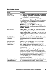
... files needed for a USB flash drive. If Boot Mode is set the emulation type to boot after 30 seconds. Hard disk allows the USB flash drive to UEFI. A device installed in the Internal SD Card slot. If the system operating system supports Unified Extensible Firmware Interface, you can set to UEFI, you install a device in this field to boot from booting if the operating system was not installed in the same boot mode. Boot Settings Screen Option Boot Mode (BIOS default) Boot Sequence Hard-Disk Drive Sequence USB Flash Drive Emulation Type (Auto default) Boot Sequence...
... files needed for a USB flash drive. If Boot Mode is set the emulation type to boot after 30 seconds. Hard disk allows the USB flash drive to UEFI. A device installed in the Internal SD Card slot. If the system operating system supports Unified Extensible Firmware Interface, you can set to UEFI, you install a device in this field to boot from booting if the operating system was not installed in the same boot mode. Boot Settings Screen Option Boot Mode (BIOS default) Boot Sequence Hard-Disk Drive Sequence USB Flash Drive Emulation Type (Auto default) Boot Sequence...

Owners Manual
Page 74
... Setup Password options to enter the correct password. Changing an Existing System Password 1 Enter the System Setup program by typing the password during POST. 2 Select the System Security screen. 3 Verify that the system has halted and must type the password and press when prompted at reboot. After the third unsuccessful attempt, the system displays an error message that the Password Status is Unlocked. 4 Type the new system password in the system password menu. Disabling...
... Setup Password options to enter the correct password. Changing an Existing System Password 1 Enter the System Setup program by typing the password during POST. 2 Select the System Security screen. 3 Verify that the system has halted and must type the password and press when prompted at reboot. After the third unsuccessful attempt, the system displays an error message that the Password Status is Unlocked. 4 Type the new system password in the system password menu. Disabling...
Owners Manual
Page 87
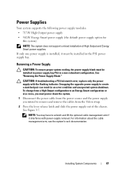
... be installed in a non-redundant configuration. See "Removing the Power Supply Blank." CAUTION: If troubleshooting a PSU mismatch error, replace only the power supply with power-supply removal. To change from a High Output configuration to an Energy Smart configuration or vice versa, you must be installed in power supply bay PS2 in the PS1 power supply bay. Power Supplies Your system supports the following power supply modules: • 717-W High Output power supply • 502-W Energy Smart power supply (the default power supply option for...
... be installed in a non-redundant configuration. See "Removing the Power Supply Blank." CAUTION: If troubleshooting a PSU mismatch error, replace only the power supply with power-supply removal. To change from a High Output configuration to an Energy Smart configuration or vice versa, you must be installed in power supply bay PS2 in the PS1 power supply bay. Power Supplies Your system supports the following power supply modules: • 717-W High Output power supply • 502-W Energy Smart power supply (the default power supply option for...

Owners Manual
Page 98
See "Opening the System." 3 Locate the SD card slot on the internal SD module and press inward on the USB memory key, see the user documentation that came with the product. 98 Installing System Components See "Boot Settings Screen." You should only perform troubleshooting and simple repairs as authorized in the System Setup program. Damage due to servicing that is not authorized by Dell is not covered by the online...
See "Opening the System." 3 Locate the SD card slot on the internal SD module and press inward on the USB memory key, see the user documentation that came with the product. 98 Installing System Components See "Boot Settings Screen." You should only perform troubleshooting and simple repairs as authorized in the System Setup program. Damage due to servicing that is not authorized by Dell is not covered by the online...

Owners Manual
Page 121
... thumbs to install the remaining memory modules. Installing System Components 121 Installing and Removing a Memory Module 1 2 3 1 memory module 3 alignment key 2 memory module socket ejectors (2) 6 Align the memory module's edge connector with the alignment key of this procedure to lock the memory module into the socket. See "Closing the System." 10 Start up the system, press to enter the System Setup program, and check the System Memory setting on...
... thumbs to install the remaining memory modules. Installing System Components 121 Installing and Removing a Memory Module 1 2 3 1 memory module 3 alignment key 2 memory module socket ejectors (2) 6 Align the memory module's edge connector with the alignment key of this procedure to lock the memory module into the socket. See "Closing the System." 10 Start up the system, press to enter the System Setup program, and check the System Memory setting on...

Owners Manual
Page 123
... for the heat sink to upgrading your system, download and install the latest system BIOS version from the processor. 6 Open the other heat-sink retention latch. Installing System Components 123 Damage due to servicing that came with the product. 1 Prior to loosen from support.dell.com. Read and follow the safety instructions that is not authorized by Dell is necessary to maintain...
... for the heat sink to upgrading your system, download and install the latest system BIOS version from the processor. 6 Open the other heat-sink retention latch. Installing System Components 123 Damage due to servicing that came with the product. 1 Prior to loosen from support.dell.com. Read and follow the safety instructions that is not authorized by Dell is necessary to maintain...
Owners Manual
Page 125
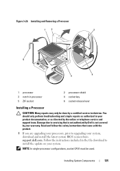
... online or telephone service and support team. Follow the instructions included in processor 5 ZIF socket 2 processor shield 4 socket key 6 socket-release lever Installing a Processor CAUTION: Many repairs may only be used. Installing System Components 125 Figure 3-20. You should only perform troubleshooting and simple repairs as authorized in your system, download and install the latest system BIOS version from support.dell.com. NOTE: In single-processor configurations, socket CPU1 must...
... online or telephone service and support team. Follow the instructions included in processor 5 ZIF socket 2 processor shield 4 socket key 6 socket-release lever Installing a Processor CAUTION: Many repairs may only be used. Installing System Components 125 Figure 3-20. You should only perform troubleshooting and simple repairs as authorized in your system, download and install the latest system BIOS version from support.dell.com. NOTE: In single-processor configurations, socket CPU1 must...
Owners Manual
Page 144
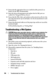
... data transmission speed and duplex. See "Installing System Components." • Hard drives • SD cards • USB memory key • NIC hardware key • Internal SD Module • Expansion cards and both expansion-card risers • Integrated storage controller • iDRAC6 Enterprise card • Power supplies 144 Troubleshooting Your System 4 Ensure that the NICs, hubs, and switches on the network are all set to servicing that the NIC ports are enabled. If all network cables are...
... data transmission speed and duplex. See "Installing System Components." • Hard drives • SD cards • USB memory key • NIC hardware key • Internal SD Module • Expansion cards and both expansion-card risers • Integrated storage controller • iDRAC6 Enterprise card • Power supplies 144 Troubleshooting Your System 4 Ensure that the NICs, hubs, and switches on the network are all set to servicing that the NIC ports are enabled. If all network cables are...
Owners Manual
Page 147
... error, replace only the power supply with a single power supply), heat sink blank (in single processor configurations), or front or back filler panel. • Ambient temperature is too high. • External airflow is obstructed. • Cables inside the system obstruct airflow. • An individual cooling fan is functioning properly. You should only perform troubleshooting and simple repairs as directed by Dell is working properly. See "Expansion Card Installation Guidelines." Troubleshooting...
... error, replace only the power supply with a single power supply), heat sink blank (in single processor configurations), or front or back filler panel. • Ambient temperature is too high. • External airflow is obstructed. • Cables inside the system obstruct airflow. • An individual cooling fan is functioning properly. You should only perform troubleshooting and simple repairs as directed by Dell is working properly. See "Expansion Card Installation Guidelines." Troubleshooting...
Owners Manual
Page 175
.... Allows hard drives to report errors and failures to remotely monitor and manage workstations. A BIOS-based program that tells a system what hardware is stored in NVRAM, any settings remain in an array, but only uses a portion of your system's hardware and customize the system's operation by setting features such as the processor(s), RAM, controllers for operation. TB - SAS - SATA - SCSI - Secure digital flash memory card. SDDC - sec - serial port - A legacy I /O bus interface. Self-Monitoring Analysis...
.... Allows hard drives to report errors and failures to remotely monitor and manage workstations. A BIOS-based program that tells a system what hardware is stored in NVRAM, any settings remain in an array, but only uses a portion of your system's hardware and customize the system's operation by setting features such as the processor(s), RAM, controllers for operation. TB - SAS - SATA - SCSI - Secure digital flash memory card. SDDC - sec - serial port - A legacy I /O bus interface. Self-Monitoring Analysis...

Owners Manual
Page 176
... cable. UPS - A battery-powered unit that automatically supplies power to your monitor must support the resolution. 176 Glossary V - video memory - Most VGA and SVGA video adapters include memory chips in a series, you must be an expansion card that a program can be integrated into the system board or may need to enable or disable the termination on these devices by changing jumper or switch settings on a network hub or switch used to manage system resources-memory, disk drives, or printers, for the devices...
... cable. UPS - A battery-powered unit that automatically supplies power to your monitor must support the resolution. 176 Glossary V - video memory - Most VGA and SVGA video adapters include memory chips in a series, you must be an expansion card that a program can be integrated into the system board or may need to enable or disable the termination on these devices by changing jumper or switch settings on a network hub or switch used to manage system resources-memory, disk drives, or printers, for the devices...

Owners Manual
Page 179
...panel board installing, 132 removing, 131 control panel display module installing, 131 removing, 129 cooling fan replacing, 106 cooling fans troubleshooting, 148 cover closing, 81 opening, 80 D Dell contacting, 167 Dell PowerEdge Diagnostics using, 159 Index 179 Index A Advanced ECC memory mode, 117 B back-panel features, 19 batteries troubleshooting, 146 battery troubleshooting the RAID card battery, 153 battery (RAID) installing, 114 removing, 114 battery (system) replacing, 127 bezel, 78 blank hard drive, 82 power supply, 89 C cabling optical drive, 108 CD/DVD drive See optical drive...
...panel board installing, 132 removing, 131 control panel display module installing, 131 removing, 129 cooling fan replacing, 106 cooling fans troubleshooting, 148 cover closing, 81 opening, 80 D Dell contacting, 167 Dell PowerEdge Diagnostics using, 159 Index 179 Index A Advanced ECC memory mode, 117 B back-panel features, 19 batteries troubleshooting, 146 battery troubleshooting the RAID card battery, 153 battery (RAID) installing, 114 removing, 114 battery (system) replacing, 127 bezel, 78 blank hard drive, 82 power supply, 89 C cabling optical drive, 108 CD/DVD drive See optical drive...

Owners Manual
Page 182
...87 replacing, 88 troubleshooting, 146 power supply blank, 89 processor installing, 125 removing, 122 troubleshooting, 157 R RAID battery installing, 114 removing, 114 remote access controller See iDRAC. P password setup, 74 system, 72 passwords disabling, 163 PERC 6/I battery cable, 114 removing bezel, 78 control panel board, 131 control panel display module, 129 cover, 80 expansion card, 92 hard drive blank, 82 hard drive from a drive carrier, 85 hard drives, 83 information tag, 79 internal USB cable, 99 memory modules, 122 power supply, 87 power supply blank, 89 processor, 122 RAID battery...
...87 replacing, 88 troubleshooting, 146 power supply blank, 89 processor installing, 125 removing, 122 troubleshooting, 157 R RAID battery installing, 114 removing, 114 remote access controller See iDRAC. P password setup, 74 system, 72 passwords disabling, 163 PERC 6/I battery cable, 114 removing bezel, 78 control panel board, 131 control panel display module, 129 cover, 80 expansion card, 92 hard drive blank, 82 hard drive from a drive carrier, 85 hard drives, 83 information tag, 79 internal USB cable, 99 memory modules, 122 power supply, 87 power supply blank, 89 processor, 122 RAID battery...
Owners Manual
Page 184
hard drive, 152 internal USB key, 150-151 keyboard, 142 memory, 148 NIC, 143 optical drive, 151 power supplies, 146 processors, 157 SAS RAID controller daughter card, 153 SD card, 150-151 system cooling, 147 system startup failure, 141 tape drive, 154 video, 142 wet system, 144 V video back-panel connector, 19 front-panel connectors, 12 troubleshooting, 142 W warning messages, 54 warranty, 55 wet system troubleshooting, 144 U UEFI Boot Manager entering, 70 main screen, 71 System Utilities screen, 72 UEFI Boot Settings screen, 71 USB front-panel connectors, 12 USB cable internal installing, ...
hard drive, 152 internal USB key, 150-151 keyboard, 142 memory, 148 NIC, 143 optical drive, 151 power supplies, 146 processors, 157 SAS RAID controller daughter card, 153 SD card, 150-151 system cooling, 147 system startup failure, 141 tape drive, 154 video, 142 wet system, 144 V video back-panel connector, 19 front-panel connectors, 12 troubleshooting, 142 W warning messages, 54 warranty, 55 wet system troubleshooting, 144 U UEFI Boot Manager entering, 70 main screen, 71 System Utilities screen, 72 UEFI Boot Settings screen, 71 USB front-panel connectors, 12 USB cable internal installing, ...


