
Installation and Service Manual
Page 3
... XR5610 20 Locating the Express Service Code and Service Tag 21 System information labels...23 Rail sizing and rack compatibility matrix...27 Chapter 3: Technical specifications 28 Chassis dimensions...29 System weight...30 Processor specifications...30 PSU specifications...30 Supported operating systems...32 Cooling fans specifications...32 System battery specifications...32 Expansion card riser specifications...32 Memory specifications...33 Storage controller specifications...33 Drives specifications...34 Ports and connectors specifications...34 USB ports specifications...34 Display port...
... XR5610 20 Locating the Express Service Code and Service Tag 21 System information labels...23 Rail sizing and rack compatibility matrix...27 Chapter 3: Technical specifications 28 Chassis dimensions...29 System weight...30 Processor specifications...30 PSU specifications...30 Supported operating systems...32 Cooling fans specifications...32 System battery specifications...32 Expansion card riser specifications...32 Memory specifications...33 Storage controller specifications...33 Drives specifications...34 Ports and connectors specifications...34 USB ports specifications...34 Display port...

Installation and Service Manual
Page 12
... Integrated Dell Remote Access Controller User's Guide at www.dell.com/ poweredgemanuals. rear view for PowerEdge XR5610 Figure 5. System configurations - For more information, see the Status LED indicators section. 2 Drives N/A Enables you to 4 x 2.5-inch SAS/SATA/NVMe SSD drives. 3 Express service tag N/A The Express service tag is a slide-out label panel that contains Service Tag, iDRAC MAC address and LOM 1 MAC address. 4 Power button Indicates if the system is powered on or off the system. 5 USB 2.0 port This port is USB 2.0compliant...
... Integrated Dell Remote Access Controller User's Guide at www.dell.com/ poweredgemanuals. rear view for PowerEdge XR5610 Figure 5. System configurations - For more information, see the Status LED indicators section. 2 Drives N/A Enables you to 4 x 2.5-inch SAS/SATA/NVMe SSD drives. 3 Express service tag N/A The Express service tag is a slide-out label panel that contains Service Tag, iDRAC MAC address and LOM 1 MAC address. 4 Power button Indicates if the system is powered on or off the system. 5 USB 2.0 port This port is USB 2.0compliant...

Installation and Service Manual
Page 13
... iDRAC network settings is set to 4x 2.5-inch SAS/SATA/NVMe SSD drives. 3 Express service tag N/A The Express service tag is a RJ-45 port. Enables you to connect PCIe expansion card installed on the rear view of Front Accessed configuration (continued) Item Ports, panels, and slots Icon Description ● Status LED: Enables you to install up to remotely access iDRAC. Table 3. For more information, see the iDRAC User's Guide at www.dell.com/ poweredgemanuals. Features available on the front view of the Rear Accessed configuration...
... iDRAC network settings is set to 4x 2.5-inch SAS/SATA/NVMe SSD drives. 3 Express service tag N/A The Express service tag is a RJ-45 port. Enables you to connect PCIe expansion card installed on the rear view of Front Accessed configuration (continued) Item Ports, panels, and slots Icon Description ● Status LED: Enables you to install up to remotely access iDRAC. Table 3. For more information, see the iDRAC User's Guide at www.dell.com/ poweredgemanuals. Features available on the front view of the Rear Accessed configuration...
Installation and Service Manual
Page 27
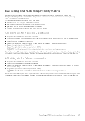
... potential interferences with rear mounted PDUs or the rear rack door A27 sliding rails for Pelican custom racks ● Support stab-in installation of the chassis to the rails. ● Support for tooled installation in 2-post rack. ● Support full extension of the system out of the rack to allow serviceability of key internal components. The document provides the information that is listed below: ● Specific details about the rail solutions compatible with...
... potential interferences with rear mounted PDUs or the rear rack door A27 sliding rails for Pelican custom racks ● Support stab-in installation of the chassis to the rails. ● Support for tooled installation in 2-post rack. ● Support full extension of the system out of the rack to allow serviceability of key internal components. The document provides the information that is listed below: ● Specific details about the rail solutions compatible with...
Installation and Service Manual
Page 45
... clear the web browser cache before downloading the drivers and firmware. Go to a USB drive, CD, or DVD. On the displayed product page, click Drivers & Downloads. Table 40. Initial system setup and configuration 45 Prerequisites Ensure that are displayed. 4. iDRAC virtual media Integrated Dell Remote Access Controller User's Guide at https://www.dell.com/idracmanuals or for system specific Integrated Dell Remote Access Controller User's Guide, go to download or install OS drivers, see https://www.dell.com/support/article/sln000178115. Enter the Service...
... clear the web browser cache before downloading the drivers and firmware. Go to a USB drive, CD, or DVD. On the displayed product page, click Drivers & Downloads. Table 40. Initial system setup and configuration 45 Prerequisites Ensure that are displayed. 4. iDRAC virtual media Integrated Dell Remote Access Controller User's Guide at https://www.dell.com/idracmanuals or for system specific Integrated Dell Remote Access Controller User's Guide, go to download or install OS drivers, see https://www.dell.com/support/article/sln000178115. Enter the Service...
Installation and Service Manual
Page 47
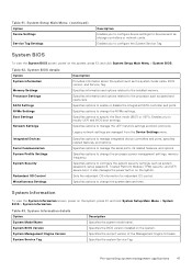
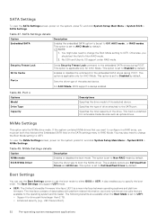
... Menu (continued) Option Device Settings Service Tag Settings Description Enables you to configure the System Service Tag. System BIOS To view the System BIOS screen, power on the system, press F2, and click System Setup Main Menu > System BIOS > System Information. Boot Settings Specifies options to enable or disable the integrated SATA controller and ports. Specifies options to configure device settings for redundant OS control. Table 43. System Management Engine Version Specifies the current version of the Management Engine firmware. System Service...
... Menu (continued) Option Device Settings Service Tag Settings Description Enables you to configure the System Service Tag. System BIOS To view the System BIOS screen, power on the system, press F2, and click System Setup Main Menu > System BIOS > System Information. Boot Settings Specifies options to enable or disable the integrated SATA controller and ports. Specifies options to configure device settings for redundant OS control. Table 43. System Management Engine Version Specifies the current version of the Management Engine firmware. System Service...
Installation and Service Manual
Page 52
..., boot and runtime service calls that you want to configure in a RAID array, you must set to Non-RAID mode by default. You may also need to change the Boot Mode setting to specify the boot order. Table 49. Enables or disables the command for AHCI Mode. This option is set the boot mode to either BIOS or UEFI. NVMe Settings This option sets the NVMe drive mode. The Boot Settings only support UEFI mode. ● UEFI: The Unified Extensible Firmware Interface (UEFI) is always enabled. The...
..., boot and runtime service calls that you want to configure in a RAID array, you must set to Non-RAID mode by default. You may also need to change the Boot Mode setting to specify the boot order. Table 49. Enables or disables the command for AHCI Mode. This option is set the boot mode to either BIOS or UEFI. NVMe Settings This option sets the NVMe drive mode. The Boot Settings only support UEFI mode. ● UEFI: The Unified Extensible Firmware Interface (UEFI) is always enabled. The...

Installation and Service Manual
Page 53
... to be UEFI-compatible to UEFI disables the BIOS Boot Settings menu. If you can only be attempted first. When set to Reset and the system fails to none when deleting variables. Enables or disables UEFI Boot options. When this option is a onetime option, will be installed from the UEFI boot mode. Hard-disk Drive Placeholder Enables or disables the Hard-disk drive placeholder. CAUTION: Switching the boot mode may prevent the system from that mode. DOS and 32-bit operating systems...
... to be UEFI-compatible to UEFI disables the BIOS Boot Settings menu. If you can only be attempted first. When set to Reset and the system fails to none when deleting variables. Enables or disables UEFI Boot options. When this option is a onetime option, will be installed from the UEFI boot mode. Hard-disk Drive Placeholder Enables or disables the Hard-disk drive placeholder. CAUTION: Switching the boot mode may prevent the system from that mode. DOS and 32-bit operating systems...

Installation and Service Manual
Page 57
..., NIC 3, and NIC 4. Table 59. This option is set to Disabled by authorized users without resetting the system. Selecting Only Back Ports On disables the front USB ports; The iDRAC Direct USB port is complete, the USB ports will be enabled or disabled dynamically by default. When set to OFF, iDRAC does not detect any USB devices installed in certain USB ports during POST. DHCP Enables and disables the DHCP for this NVMe-oF connection. Host IP Address Specifies...
..., NIC 3, and NIC 4. Table 59. This option is set to Disabled by authorized users without resetting the system. Selecting Only Back Ports On disables the front USB ports; The iDRAC Direct USB port is complete, the USB ports will be enabled or disabled dynamically by default. When set to OFF, iDRAC does not detect any USB devices installed in certain USB ports during POST. DHCP Enables and disables the DHCP for this NVMe-oF connection. Host IP Address Specifies...

Installation and Service Manual
Page 58
... USB Type B port connection on the system, press F2, and click System Setup Main Menu > System BIOS > Serial Communication. Auto Discovery Bifurcation Settings allows Platform Default Bifurcation, Auto Discovery of your system stops responding, this option is set to Enabled, the Embedded Video Controller will be disabled right before the operating system boots. BIOS will then be the primary display even if add-in graphics card is installed), then the Embedded Video Controller is set...
... USB Type B port connection on the system, press F2, and click System Setup Main Menu > System BIOS > Serial Communication. Auto Discovery Bifurcation Settings allows Platform Default Bifurcation, Auto Discovery of your system stops responding, this option is set to Enabled, the Embedded Video Controller will be disabled right before the operating system boots. BIOS will then be the primary display even if add-in graphics card is installed), then the Embedded Video Controller is set...
Installation and Service Manual
Page 66
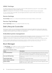
... the Dell Lifecycle Controller, configuring hardware and firmware, and deploying the operating system, see Dell Integrated Dell Remote Access Controller User's Guide at https://www.dell.com/idracmanuals. NOTE: Accessing some of the features on the system and press F11. LC is started during the boot sequence and functions independently of features provided by using the iDRAC settings. Boot Manager The Boot Manager option enables you to select boot options and diagnostic utilities. Service Tag Settings Service Tag Settings enables you to configure...
... the Dell Lifecycle Controller, configuring hardware and firmware, and deploying the operating system, see Dell Integrated Dell Remote Access Controller User's Guide at https://www.dell.com/idracmanuals. NOTE: Accessing some of the features on the system and press F11. LC is started during the boot sequence and functions independently of features provided by using the iDRAC settings. Boot Manager The Boot Manager option enables you to select boot options and diagnostic utilities. Service Tag Settings Service Tag Settings enables you to configure...
Installation and Service Manual
Page 132
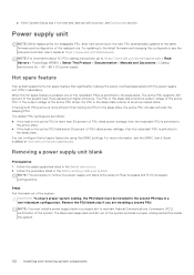
... https://www.dell.com/poweredgemanuals > Rack Servers > PowerEdge XR5610 > Select This Product > Documentation > Manuals and Documents > Cabling instructions for Rear Accessed and Front Accessed configurations. If the output voltage of the replaced one PSU in proper cooling and airflow inside your system. e. NOTE: For information about DC PSU cabling instructions, go to remove the power supply unit blank is more information, see the Lifecycle Controller User's Guide at higher efficiency. Enter System Setup and if...
... https://www.dell.com/poweredgemanuals > Rack Servers > PowerEdge XR5610 > Select This Product > Documentation > Manuals and Documents > Cabling instructions for Rear Accessed and Front Accessed configurations. If the output voltage of the replaced one PSU in proper cooling and airflow inside your system. e. NOTE: For information about DC PSU cabling instructions, go to remove the power supply unit blank is more information, see the Lifecycle Controller User's Guide at higher efficiency. Enter System Setup and if...
Installation and Service Manual
Page 147
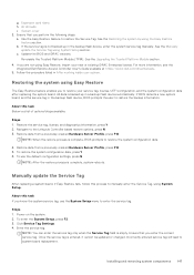
... reboots. Update the BIOS and iDRAC versions. Ensure that you know the system service tag, use the default configuration settings, press N NOTE: After the restore process is a list of options/steps available: Steps 1. If the service tag is backed up in a backup flash device automatically. For more information, see the Integrated Dell Remote Access Controller User's Guide available at https://www.dell.com/idracmanuals.. 5. Air shrouds i. Re-enable the Trusted Platform Module...
... reboots. Update the BIOS and iDRAC versions. Ensure that you know the system service tag, use the default configuration settings, press N NOTE: After the restore process is a list of options/steps available: Steps 1. If the service tag is backed up in a backup flash device automatically. For more information, see the Integrated Dell Remote Access Controller User's Guide available at https://www.dell.com/idracmanuals.. 5. Air shrouds i. Re-enable the Trusted Platform Module...
Installation and Service Manual
Page 175
Secure Connect Gateway (SCG) monitors your devices and uploads it securely to troubleshoot the issue. ● Proactive contact - When an issue is used by Dell Technical Support to Dell. The available benefits vary depending on the Dell Service entitlement purchased for your Dell server, storage, and networking devices. For more information about the support case and helps you resolve the issue. By installing and setting up a Secure Connect Gateway (SCG) application...
Secure Connect Gateway (SCG) monitors your devices and uploads it securely to troubleshoot the issue. ● Proactive contact - When an issue is used by Dell Technical Support to Dell. The available benefits vary depending on the Dell Service entitlement purchased for your Dell server, storage, and networking devices. For more information about the support case and helps you resolve the issue. By installing and setting up a Secure Connect Gateway (SCG) application...
iDRAC9 Version 6.10.25.00 Release Notes
Page 4
... firmware update through LifeCycle controller(LC) GUI, the component information displayed in a read-only drive that you use the 'Include Password Hash' option. 13. During OS deployment through downloads.dell.com, adding catalog location or name is active for Idle server detection feature related attributes to use the mouse to a group manager of a warm reboot. 5. This device will not reset. After the OS installation is upgraded to factory defaults and...
... firmware update through LifeCycle controller(LC) GUI, the component information displayed in a read-only drive that you use the 'Include Password Hash' option. 13. During OS deployment through downloads.dell.com, adding catalog location or name is active for Idle server detection feature related attributes to use the mouse to a group manager of a warm reboot. 5. This device will not reset. After the OS installation is upgraded to factory defaults and...
iDRAC9 Version 6.10.25.00 Release Notes
Page 5
... controller data option in the firmware inventory page. 4. For staged operations that are no longer display OS Collector application separately in System category and retry the update. 2. AD/LDAP diagnostic results will no longer performed while running . To change detected for HBA, BOSS, or NVME drives. 8. To resolve the issue, reset iDRAC using RACADM, WSMAN, or Redfish interface, it is installed with iDRAC Service Module version 4.0.1 and later versions...
... controller data option in the firmware inventory page. 4. For staged operations that are no longer display OS Collector application separately in System category and retry the update. 2. AD/LDAP diagnostic results will no longer performed while running . To change detected for HBA, BOSS, or NVME drives. 8. To resolve the issue, reset iDRAC using RACADM, WSMAN, or Redfish interface, it is installed with iDRAC Service Module version 4.0.1 and later versions...
iDRAC9 Version 6.10.25.00 Release Notes
Page 7
.... Upgrade the Rsyslog server to iDRAC. 12. Performing GET method on Trusted Platform Module enablement. 6. Following SSH configurations are run on iDRAC: KEX algorithms: a. [email protected] 7. Storage 1. Due to the latest version. When FCP is enabled, 'Default Password Warning' setting is disabled after the iDRAC is updated to a DMTF tool limitation, the URIs for iDRAC firmware is not supported. 3. Servers with NVMe drives with TLS version 1.3 is displayed...
.... Upgrade the Rsyslog server to iDRAC. 12. Performing GET method on Trusted Platform Module enablement. 6. Following SSH configurations are run on iDRAC: KEX algorithms: a. [email protected] 7. Storage 1. Due to the latest version. When FCP is enabled, 'Default Password Warning' setting is disabled after the iDRAC is updated to a DMTF tool limitation, the URIs for iDRAC firmware is not supported. 3. Servers with NVMe drives with TLS version 1.3 is displayed...

iDRAC9 Version 6.10.25.00 Release Notes
Page 8
... more information, see Intel's documentation for the specific device. 7. SMART monitoring is disabled for SWRAID controllers are supported only on the system configuration. Read-only mode d. Virtual console may not function on Safari browser while iDRAC is set to enable or disable the disk cache policy for a hard drive while it with two PSUs while upgrade option is recommended to use the Dell supported SATA, SAS, or NVMe drives. The option to version 1.2 or above. 4. iDRAC...
... more information, see Intel's documentation for the specific device. 7. SMART monitoring is disabled for SWRAID controllers are supported only on the system configuration. Read-only mode d. Virtual console may not function on Safari browser while iDRAC is set to enable or disable the disk cache policy for a hard drive while it with two PSUs while upgrade option is recommended to use the Dell supported SATA, SAS, or NVMe drives. The option to version 1.2 or above. 4. iDRAC...

iDRAC9 Version 6.10.25.00 Release Notes
Page 10
... FC adapters are configured to predicted failure. In certain cases, Group Manager Jobs view may not display the updated state due to boot from FC storage arrays using the RACADM command racadm lclog view. 2. If the LCD display is enabled, the port numbers displayed on the LC Network Settings page (Settings > Network Settings) do not match the port numbers displayed on the LCD before inserting a USB storage device. 4. LC UI supports share names and file paths that of a faulty part, use may...
... FC adapters are configured to predicted failure. In certain cases, Group Manager Jobs view may not display the updated state due to boot from FC storage arrays using the RACADM command racadm lclog view. 2. If the LCD display is enabled, the port numbers displayed on the LC Network Settings page (Settings > Network Settings) do not match the port numbers displayed on the LCD before inserting a USB storage device. 4. LC UI supports share names and file paths that of a faulty part, use may...
iDRAC9 Version 6.10.25.00 Release Notes
Page 11
... PowerEdge M640-VRTX chassis are different, LC displays a warning message. This has no impact on the following could not be validated. Deployment of Windows Server operating systems (OS) using the Network Configuration page of LC UI, the following error message: A required CD/DVD drive device driver is the version of Lifecycle Controller GUI, the IP Address Source for both versions, and displays an error if the network details for hot-plugged NVMe disks. If the operation continues to fail...
... PowerEdge M640-VRTX chassis are different, LC displays a warning message. This has no impact on the following could not be validated. Deployment of Windows Server operating systems (OS) using the Network Configuration page of LC UI, the following error message: A required CD/DVD drive device driver is the version of Lifecycle Controller GUI, the IP Address Source for both versions, and displays an error if the network details for hot-plugged NVMe disks. If the operation continues to fail...


