Getting Started Guide
Page 5
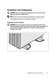
... Started With Your System 3 NOTE: If you are using the optional rack configuration, assemble the rails and install the system in the rack following procedure, review the safety instructions that can be extended outward to the system. Failure to extend the feet poses the risk of having the system tip over...
... Started With Your System 3 NOTE: If you are using the optional rack configuration, assemble the rails and install the system in the rack following procedure, review the safety instructions that can be extended outward to the system. Failure to extend the feet poses the risk of having the system tip over...

Hardware Owner's Manual
Page 30
... power supply's Check the AC power AC input is no longer redundant. If the remaining power supply fails, the system will shut down. power supply. Review & clear SEL. If the problem persists, see "Troubleshooting Power Supplies" on page 193. 30 About Your System E1624 Lost power supply redundancy. See "Troubleshooting Power...
... power supply's Check the AC power AC input is no longer redundant. If the remaining power supply fails, the system will shut down. power supply. Review & clear SEL. If the problem persists, see "Troubleshooting Power Supplies" on page 193. 30 About Your System E1624 Lost power supply redundancy. See "Troubleshooting Power...

Hardware Owner's Manual
Page 31
The system BIOS has Check the SEL for 10 seconds and restart the system. for more Review & clear determined there has been information and then SEL. If on a component that the problem persists, see resides in PCI "Troubleshooting configuration space at bus ... determine its AC power to the system origin. If on a component that the problem persists, see resides in the system, but clear the SEL. Table 1-1. Review & clear SEL. E171F PCIe fatal error on ##, device ##, function page 178. ##. About Your System 31
The system BIOS has Check the SEL for 10 seconds and restart the system. for more Review & clear determined there has been information and then SEL. If on a component that the problem persists, see resides in PCI "Troubleshooting configuration space at bus ... determine its AC power to the system origin. If on a component that the problem persists, see resides in the system, but clear the SEL. Table 1-1. Review & clear SEL. E171F PCIe fatal error on ##, device ##, function page 178. ##. About Your System 31

Hardware Owner's Manual
Page 32
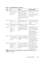
.... E1A1D Control panel USB cable not detected. Table 1-1. LCD Status Messages (continued) Code Text Causes Corrective Actions E1810 Hard drive ## The specified hard drive fault. Review has experienced a fault. & clear SEL. E1920 iDRAC6 Upgrade The iDRAC6 Express card If the problem persists, Failed is not installed properly or see "Getting Help...
.... E1A1D Control panel USB cable not detected. Table 1-1. LCD Status Messages (continued) Code Text Causes Corrective Actions E1810 Hard drive ## The specified hard drive fault. Review has experienced a fault. & clear SEL. E1920 iDRAC6 Upgrade The iDRAC6 Express card If the problem persists, Failed is not installed properly or see "Getting Help...

Hardware Owner's Manual
Page 35
... screen for specific failure during error messages. not enable memory Check DIMMs. mirroring because of a faulty memory module or an invalid memory configuration. cycle AC. Review User Guide. E2022 General General failure after video. If the problem persists, see "Getting Help" on page 193. See "Troubleshooting the Processors" on Check DIMMs...
... screen for specific failure during error messages. not enable memory Check DIMMs. mirroring because of a faulty memory module or an invalid memory configuration. cycle AC. Review User Guide. E2022 General General failure after video. If the problem persists, see "Getting Help" on page 193. See "Troubleshooting the Processors" on Check DIMMs...
Hardware Owner's Manual
Page 37
... and what the power supply can hardware configuration or config. requires more . provide. power supplies, and then restart the system. A Check the SEL for details Review & clear and is unable to log any on the events. messages can boot if install higher-wattage configuration. I1912 SEL full. The SEL is full... events, then clear log. NOTE: For the full name of charge left. LCD overflow message. W1627 Power required The system configuration Turn off power to review all Errors. About Your System 37
... and what the power supply can hardware configuration or config. requires more . provide. power supplies, and then restart the system. A Check the SEL for details Review & clear and is unable to log any on the events. messages can boot if install higher-wattage configuration. I1912 SEL full. The SEL is full... events, then clear log. NOTE: For the full name of charge left. LCD overflow message. W1627 Power required The system configuration Turn off power to review all Errors. About Your System 37

Hardware Owner's Manual
Page 44
.... Gate A20 failure Faulty keyboard controller; Invalid configuration information please run SETUP program. Mouse or keyboard cable is operational. Run the System Setup program and review the current settings. Remove the PCIe expansion card and install the integrated storage controller in the dedicated storage controller slot. Table 1-2. See Management "Troubleshooting a NIC...
.... Gate A20 failure Faulty keyboard controller; Invalid configuration information please run SETUP program. Mouse or keyboard cable is operational. Run the System Setup program and review the current settings. Remove the PCIe expansion card and install the integrated storage controller in the dedicated storage controller slot. Table 1-2. See Management "Troubleshooting a NIC...

Hardware Owner's Manual
Page 79
... you begin this chapter assume that came with the system. Installing System Components 79 Installing System Components NOTE: The procedures and figures in this procedure, review the safety instructions that your system is in a rack configuration, disregard any of the components inside the system.
... you begin this chapter assume that came with the system. Installing System Components 79 Installing System Components NOTE: The procedures and figures in this procedure, review the safety instructions that your system is in a rack configuration, disregard any of the components inside the system.
Hardware Owner's Manual
Page 85
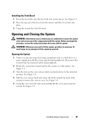
... on the cover release latch counterclockwise to the unlocked position. Installing System Components 85 WARNING: Whenever you . Opening the System 1 Unless you begin this procedure, review the safety instructions that came with the system. See Figure 3-4. 4 Pull the cover release latch and rotate the latch towards the back of the bezel...
... on the cover release latch counterclockwise to the unlocked position. Installing System Components 85 WARNING: Whenever you . Opening the System 1 Unless you begin this procedure, review the safety instructions that came with the system. See Figure 3-4. 4 Pull the cover release latch and rotate the latch towards the back of the bezel...

Hardware Owner's Manual
Page 87
... trained service technicians are authorized to remove the system cover and access any peripherals and connect the system to cool before you begin this procedure, review the safety instructions that came with the cooling shroud removed. CAUTION: Never operate your system with the system. Overheating of the system can get very...
... trained service technicians are authorized to remove the system cover and access any peripherals and connect the system to cool before you begin this procedure, review the safety instructions that came with the cooling shroud removed. CAUTION: Never operate your system with the system. Overheating of the system can get very...

Hardware Owner's Manual
Page 94
... the system. Optical and Tape Drives The 5.25-inch drive bays at the front of the drive. See Figure 3-10. 7 If you begin this procedure, review the safety instructions that came with the system. 1 Turn off the system, including any peripherals and connect the system to release the shoulder screw and...
... the system. Optical and Tape Drives The 5.25-inch drive bays at the front of the drive. See Figure 3-10. 7 If you begin this procedure, review the safety instructions that came with the system. 1 Turn off the system, including any peripherals and connect the system to release the shoulder screw and...

Hardware Owner's Manual
Page 96
... the cable in between be unterminated. b SCSI logic requires that came with the drive. If you are installing a SAS tape drive, you begin this procedure, review the safety instructions that came with other devices on the following guidelines: a Each device attached to a SCSI host adapter must configure the tape drive according...
... the cable in between be unterminated. b SCSI logic requires that came with the drive. If you are installing a SAS tape drive, you begin this procedure, review the safety instructions that came with other devices on the following guidelines: a Each device attached to a SCSI host adapter must configure the tape drive according...

Hardware Owner's Manual
Page 104
... on the memory module. 1 Turn off the system, including any attached peripherals, and disconnect the system from the sockets in which you begin this procedure, review the safety instructions that came with the system. Handle the memory modules by the card edges and avoid touching the components on each memory module...
... on the memory module. 1 Turn off the system, including any attached peripherals, and disconnect the system from the sockets in which you begin this procedure, review the safety instructions that came with the system. Handle the memory modules by the card edges and avoid touching the components on each memory module...

Hardware Owner's Manual
Page 106
Repeat step 5 through step 8 of this procedure, review the safety instructions that the memory modules are firmly seated in their sockets. 18 Run the system memory test in the system diagnostics. See "Running ...
Repeat step 5 through step 8 of this procedure, review the safety instructions that the memory modules are firmly seated in their sockets. 18 Run the system memory test in the system diagnostics. See "Running ...

Hardware Owner's Manual
Page 107
...stored power prior to install the update on page 87. See Figure 3-12. 6 Wait 30 seconds for 3 seconds to loosen from support.dell.com and follow the instructions included in the interior of the components inside the system. When disconnected from AC power, press and hold the ... Open the system. Processors Removing a Processor WARNING: Only trained service technicians are hot to remove the processor. Before you begin this procedure, review the safety instructions that you intend to the touch for some time after the system has been powered down. 9 Place the system upright and...
...stored power prior to install the update on page 87. See Figure 3-12. 6 Wait 30 seconds for 3 seconds to loosen from support.dell.com and follow the instructions included in the interior of the components inside the system. When disconnected from AC power, press and hold the ... Open the system. Processors Removing a Processor WARNING: Only trained service technicians are hot to remove the processor. Before you begin this procedure, review the safety instructions that you intend to the touch for some time after the system has been powered down. 9 Place the system upright and...

Hardware Owner's Manual
Page 110
.... Allow the processor to float on the ZIF socket. NOTE: In a single-processor configuration, the CPU1 socket must be used. 1 If you begin this procedure, review the safety instructions that came with the socket keys on the pins, allowing the processor shield to remove the system cover and access any of...
.... Allow the processor to float on the ZIF socket. NOTE: In a single-processor configuration, the CPU1 socket must be used. 1 If you begin this procedure, review the safety instructions that came with the socket keys on the pins, allowing the processor shield to remove the system cover and access any of...

Hardware Owner's Manual
Page 115
..., including any of the system and aid in the system. Before you begin this bracket in the expansion card tab slot. NOTE: Keep this procedure, review the safety instructions that the card's metal tab is inserted in case you are installing a new card, remove the filler bracket.
..., including any of the system and aid in the system. Before you begin this bracket in the expansion card tab slot. NOTE: Keep this procedure, review the safety instructions that the card's metal tab is inserted in case you are installing a new card, remove the filler bracket.

Hardware Owner's Manual
Page 118
See "Opening the System" on page 85. 4 Disconnect any attached peripherals, and disconnect the system from the expansion-card connector. 6 If you begin this procedure, review the safety instructions that came with the system. 1 Turn off the system, including any cables connected to the expansion card. 5 Remove the expansion card: a Open ...
See "Opening the System" on page 85. 4 Disconnect any attached peripherals, and disconnect the system from the expansion-card connector. 6 If you begin this procedure, review the safety instructions that came with the system. 1 Turn off the system, including any cables connected to the expansion card. 5 Remove the expansion card: a Open ...

Hardware Owner's Manual
Page 119
... the System" on page 85. 4 Position the module so the tabs on the underside of the components inside the system. Before you begin this procedure, review the safety instructions that came with the system. 1 Turn off the system, including any of the tray fit into the hooks on a flat surface. 3 Open...
... the System" on page 85. 4 Position the module so the tabs on the underside of the components inside the system. Before you begin this procedure, review the safety instructions that came with the system. 1 Turn off the system, including any of the tray fit into the hooks on a flat surface. 3 Open...

Hardware Owner's Manual
Page 121
Before you begin this procedure, review the safety instructions that came with the system. 1 Turn off the system, including any attached peripherals, and disconnect the system from the system board. 5 Lift ...
Before you begin this procedure, review the safety instructions that came with the system. 1 Turn off the system, including any attached peripherals, and disconnect the system from the system board. 5 Lift ...


