Hardware Owner's Manual
Page 37
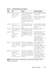
...power supplies, and then restart the system. requires more . LCD Status Messages (continued) Code Text Causes Corrective Actions I1911 LCD Log Full. I1920 iDRAC6 Upgrade iDRAC6 Express card has Information only Successful been installed correctly W1228 RAID Controller battery capacity < 24hr. If problem persists, replace... Check the SEL for 10 seconds or The eleventh message clear the SEL. requires more power than system, reduce the Check PSU and what the power supply can hardware configuration or config. I1912 SEL full. system for details Review & clear and...
...power supplies, and then restart the system. requires more . LCD Status Messages (continued) Code Text Causes Corrective Actions I1911 LCD Log Full. I1920 iDRAC6 Upgrade iDRAC6 Express card has Information only Successful been installed correctly W1228 RAID Controller battery capacity < 24hr. If problem persists, replace... Check the SEL for 10 seconds or The eleventh message clear the SEL. requires more power than system, reduce the Check PSU and what the power supply can hardware configuration or config. I1912 SEL full. system for details Review & clear and...
Hardware Owner's Manual
Page 41
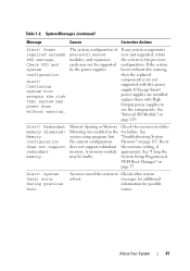
...The system configuration of processor(s), memory modules, and expansion cards may not be faulty. If Energy Smart power supplies are not supported with High Output power supplies to use the components. See "Internal SD Module" on page 167. Memory Sparing or Memory Check ...system boot accepts the risk that system may be supported by the power supplies. If the system boots without warning. messages for additional information for failure. See "Using the may power down without this warning, then the replaced component(s) are installed, replace them with this power supply.
...The system configuration of processor(s), memory modules, and expansion cards may not be faulty. If Energy Smart power supplies are not supported with High Output power supplies to use the components. See "Internal SD Module" on page 167. Memory Sparing or Memory Check ...system boot accepts the risk that system may be supported by the power supplies. If the system boots without warning. messages for additional information for failure. See "Using the may power down without this warning, then the replaced component(s) are installed, replace them with this power supply.
Hardware Owner's Manual
Page 54
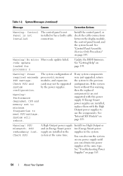
... module, the control panel board, and the system board. Warning! See "Troubleshooting Power Supplies" on page 193. Warning! Check PSU and system configuration. If Energy Smart power supplies are installed, replace them with this warning, then the replaced component(s) are installed in the supplies in the system. See "Getting Help" on page 165. 54 About Your System...
... module, the control panel board, and the system board. Warning! See "Troubleshooting Power Supplies" on page 193. Warning! Check PSU and system configuration. If Energy Smart power supplies are installed, replace them with this warning, then the replaced component(s) are installed in the supplies in the system. See "Getting Help" on page 165. 54 About Your System...

Hardware Owner's Manual
Page 156
... Board WARNING: Only trained service technicians are authorized to the plate and lift out the power distribution board. 156 Installing System Components See "Removing a Power Supply" on page 82. 3 Rotate the system feet inward and lay the system on the system and attached peripherals....2 Remove the power supplies. Before you begin this procedure, review the safety instructions that came with the system. 1 Turn off the system, including any of the components inside the system. 15 Rotate the system feet outward. 16 Replace the front bezel. b Slide the power distribution board plate...
... Board WARNING: Only trained service technicians are authorized to the plate and lift out the power distribution board. 156 Installing System Components See "Removing a Power Supply" on page 82. 3 Rotate the system feet inward and lay the system on the system and attached peripherals....2 Remove the power supplies. Before you begin this procedure, review the safety instructions that came with the system. 1 Turn off the system, including any of the components inside the system. 15 Rotate the system feet outward. 16 Replace the front bezel. b Slide the power distribution board plate...

Hardware Owner's Manual
Page 158
...Board 1 Align the securing slots on the power distribution board with the tabs on the chassis. 2 Replace the five screws securing the power distribution board to the plate. 3 Connect all the power cables to the power distribution board. 4 Lower the power distribution board plate into the chassis slightly ... surface. 10 Rotate the system feet outward. 11 Reattach any peripherals and connect the system to rest in position. 5 Replace the two screws on the power distribution board plate. 6 Replace the system board. See "Installing a Power Supply" on page 154. 7 Replace the power supplies.
...Board 1 Align the securing slots on the power distribution board with the tabs on the chassis. 2 Replace the five screws securing the power distribution board to the plate. 3 Connect all the power cables to the power distribution board. 4 Lower the power distribution board plate into the chassis slightly ... surface. 10 Rotate the system feet outward. 11 Reattach any peripherals and connect the system to rest in position. 5 Replace the two screws on the power distribution board plate. 6 Replace the system board. See "Installing a Power Supply" on page 154. 7 Replace the power supplies.

Hardware Owner's Manual
Page 164
... the system. See "Removing the Cooling Shroud" on page 87. 3 Ensure that the following components are properly connected. 5 Replace the cooling shroud. See "Installing System Components" on page 79. • Expansion cards • Power supplies • Fans • Processors and heat sinks • Memory modules • Hard-drive carriers 4 Ensure that came with...
... the system. See "Removing the Cooling Shroud" on page 87. 3 Ensure that the following components are properly connected. 5 Replace the cooling shroud. See "Installing System Components" on page 79. • Expansion cards • Power supplies • Fans • Processors and heat sinks • Memory modules • Hard-drive carriers 4 Ensure that came with...

Hardware Owner's Manual
Page 165
...In a rare case of time (for the time kept in the System Setup program, replace the battery. The power indicator turns green to speed up or slow down. Troubleshooting Power Supplies 1 Identify the faulty power supply by a defective battery. 1 Re-enter the time and date through the System Setup ... See "System Battery" on page 193. See "Power Supplies" on page 193. If the system seems to determine if it . If the problem persists, replace the faulty power supply. 3 If the problem persists, see "Getting Help" on page 144. See "Power Indicator Codes" on the system. 4 Enter the ...
...In a rare case of time (for the time kept in the System Setup program, replace the battery. The power indicator turns green to speed up or slow down. Troubleshooting Power Supplies 1 Identify the faulty power supply by a defective battery. 1 Re-enter the time and date through the System Setup ... See "System Battery" on page 193. See "Power Supplies" on page 193. If the system seems to determine if it . If the problem persists, replace the faulty power supply. 3 If the problem persists, see "Getting Help" on page 144. See "Power Indicator Codes" on the system. 4 Enter the ...

Hardware Owner's Manual
Page 205
..., 127 battery (system) replacing, 144 blank hard drive, 90-91 power supply, 83 C CD drive troubleshooting, 171 connectors USB, 20 video, 20 contacting Dell, 193 control panel assembly features, 12 installing, 148 LCD panel features, 14 removing, 145 cooling fans removing, 136 troubleshooting, 166 D damaged systems troubleshooting, 164 Dell contacting, 193 Dell PowerEdge Diagnostics using, 181 diagnostics...
..., 127 battery (system) replacing, 144 blank hard drive, 90-91 power supply, 83 C CD drive troubleshooting, 171 connectors USB, 20 video, 20 contacting Dell, 193 control panel assembly features, 12 installing, 148 LCD panel features, 14 removing, 145 cooling fans removing, 136 troubleshooting, 166 D damaged systems troubleshooting, 164 Dell contacting, 193 Dell PowerEdge Diagnostics using, 181 diagnostics...
Hardware Owner's Manual
Page 208
... integrated storage controller card, 132, 135 internal SD card, 122 internal SD module, 121 memory modules, 106 power supplies, 82 processor, 107 RAID battery, 127 replacing system battery, 144 S safety, 159 SAS controller See storage controller. SAS controller daughter card troubleshooting, 176 SAS...drives, 89 startup accessing system features, 11 storage controller card installing, 134-135 removing, 132, 135 troubleshooting, 175 support contacting Dell, 193 system cooling troubleshooting, 166 system features accessing, 11 system messages, 39 system password, 72 system setup options, 59 system...
... integrated storage controller card, 132, 135 internal SD card, 122 internal SD module, 121 memory modules, 106 power supplies, 82 processor, 107 RAID battery, 127 replacing system battery, 144 S safety, 159 SAS controller See storage controller. SAS controller daughter card troubleshooting, 176 SAS...drives, 89 startup accessing system features, 11 storage controller card installing, 134-135 removing, 132, 135 troubleshooting, 175 support contacting Dell, 193 system cooling troubleshooting, 166 system features accessing, 11 system messages, 39 system password, 72 system setup options, 59 system...


