
Hardware Owner's Manual
Page 82
... 82 Installing System Components For information about the cable management arm, see the system's rack documentation. 1 Disconnect the power cable from the Velcro strap. 2 Press the lever release latch and slide the power supply out of the chassis. See Figure 3-2. Removing a Power Supply NOTE: You may have to remove, and remove the...
... 82 Installing System Components For information about the cable management arm, see the system's rack documentation. 1 Disconnect the power cable from the Velcro strap. 2 Press the lever release latch and slide the power supply out of the chassis. See Figure 3-2. Removing a Power Supply NOTE: You may have to remove, and remove the...

Hardware Owner's Manual
Page 83
...-swapping a new power supply, allow several seconds for the system to recognize the power supply and determine whether it is functioning properly (see the system's rack documentation. 2 Connect the power cable to signify that the power supply is working properly. For information about the cable management arm, see Figure 1-6). The... a Power Supply Blank NOTE: Install the power supply blank only in a non-redundant configuration. Installing a Power Supply 1 Slide the new power supply into the chassis until the power supply is fully seated and the release latch snaps into the...
...-swapping a new power supply, allow several seconds for the system to recognize the power supply and determine whether it is functioning properly (see the system's rack documentation. 2 Connect the power cable to signify that the power supply is working properly. For information about the cable management arm, see Figure 1-6). The... a Power Supply Blank NOTE: Install the power supply blank only in a non-redundant configuration. Installing a Power Supply 1 Slide the new power supply into the chassis until the power supply is fully seated and the release latch snaps into the...
Tower-to-Rack Conversion Guide
Page 4
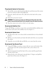
...at the back of the system chassis. 3 Rotate the system feet inward. See Figure 1-1. 4 Tower-to move the system by yourself. 4 Place the system on its side on a flat, level work surface. To prevent personal injury, do not attempt to -Rack Conversion Guide Preparing the System ...for Conversion 1 Turn off the system and attached peripherals, and disconnect the system from the system. WARNING: The system may weigh up to the system chassis. Removing the Stabilizer Feet Using a #2 Phillips ...
...at the back of the system chassis. 3 Rotate the system feet inward. See Figure 1-1. 4 Tower-to move the system by yourself. 4 Place the system on its side on a flat, level work surface. To prevent personal injury, do not attempt to -Rack Conversion Guide Preparing the System ...for Conversion 1 Turn off the system and attached peripherals, and disconnect the system from the system. WARNING: The system may weigh up to the system chassis. Removing the Stabilizer Feet Using a #2 Phillips ...
Tower-to-Rack Conversion Guide
Page 5
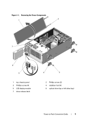
Removing the Tower Components 1 2 7 6 5 1 top chassis panel 3 Phillips screw (4) 5 LCD display module 7 drive release latch 4 3 2 Phillips screw (2) 4 stabilizer foot (4) 6 optical drive (top or left drive bay) Tower-to-Rack Conversion Guide 5 Figure 1-1.
Removing the Tower Components 1 2 7 6 5 1 top chassis panel 3 Phillips screw (4) 5 LCD display module 7 drive release latch 4 3 2 Phillips screw (2) 4 stabilizer foot (4) 6 optical drive (top or left drive bay) Tower-to-Rack Conversion Guide 5 Figure 1-1.

Tower-to-Rack Conversion Guide
Page 6
...LCD Display Module 1 Remove the optical drive from the top (or left rack ear piece. See Figure 1-2. 2 Install the three screws using a #2 Phillips screwdriver. 3 Repeat for the left ) drive bay of the optical drive. 4 Close the top chassis panel. 5 Close the system cover. b Insert the optical drive into... the lever locks into the tab slots at the bottom of the chassis. 2 Firmly press the top of the system chassis. c Slide the drive out to remove it from the back of the arrow to the horizontal rack orientation. 3 Reinstall the optical drive in the direction of the optical...
...LCD Display Module 1 Remove the optical drive from the top (or left rack ear piece. See Figure 1-2. 2 Install the three screws using a #2 Phillips screwdriver. 3 Repeat for the left ) drive bay of the optical drive. 4 Close the top chassis panel. 5 Close the system cover. b Insert the optical drive into... the lever locks into the tab slots at the bottom of the chassis. 2 Firmly press the top of the system chassis. c Slide the drive out to remove it from the back of the arrow to the horizontal rack orientation. 3 Reinstall the optical drive in the direction of the optical...


