
Hardware Owner's Manual
Page 7
... Cage 138 Removing the Fan Cage 138 Installing a Fan Cage 139 VFlash Media (Optional 140 Installing a VFlash Media 140 Removing a VFlash Media 140 Integrated Dell Remote Access Controller 6 (iDRAC6) Enterprise Card (Optional 140 Installing an iDRAC6 Enterprise Card 140 Removing an iDRAC6 Enterprise Card 142 System Battery 144 Replacing the System Battery 144 Contents 7
... Cage 138 Removing the Fan Cage 138 Installing a Fan Cage 139 VFlash Media (Optional 140 Installing a VFlash Media 140 Removing a VFlash Media 140 Integrated Dell Remote Access Controller 6 (iDRAC6) Enterprise Card (Optional 140 Installing an iDRAC6 Enterprise Card 140 Removing an iDRAC6 Enterprise Card 142 System Battery 144 Replacing the System Battery 144 Contents 7

Hardware Owner's Manual
Page 17
... of the system in Celsius or Fahrenheit. See "Setup Menu" on page 16. Displays the temperature of the Host, Model, or User String for the iDRAC6. Displays the MAC addresses for the system. Displays the Asset tag or the Service tag for DRAC, iSCSIn, or NETn. Displays the power output of...
... of the system in Celsius or Fahrenheit. See "Setup Menu" on page 16. Displays the temperature of the Host, Model, or User String for the iDRAC6. Displays the MAC addresses for the system. Displays the Asset tag or the Service tag for DRAC, iSCSIn, or NETn. Displays the power output of...
Hardware Owner's Manual
Page 22
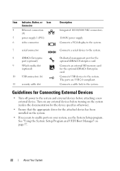
...video connector Description Integrated 10/100/1000 NIC connectors. 1100-W power supply. Connects USB devices to the system. Guidelines for the optional iDRAC6 Enterprise card. Connects an external SD memory card for Connecting External Devices • Turn off power to enable ports on page 57...use the System Setup program. Connects a VGA display to the system. 7 serial connector Connects a serial device to the system. 8 iDRAC6 Enterprise port (optional) 9 VFlash media slot (optional) 10 USB connectors (6) 11 security cable slot Dedicated management port for the attached ...
...video connector Description Integrated 10/100/1000 NIC connectors. 1100-W power supply. Connects USB devices to the system. Guidelines for the optional iDRAC6 Enterprise card. Connects an external SD memory card for Connecting External Devices • Turn off power to enable ports on page 57...use the System Setup program. Connects a VGA display to the system. 7 serial connector Connects a serial device to the system. 8 iDRAC6 Enterprise port (optional) 9 VFlash media slot (optional) 10 USB connectors (6) 11 security cable slot Dedicated management port for the attached ...

Hardware Owner's Manual
Page 32
Information only. E1920 iDRAC6 Upgrade The iDRAC6 Express card If the problem persists, Failed is not installed properly or see "Getting Help" on page 167. 32 About Your System If the failure. ...
Information only. E1920 iDRAC6 Upgrade The iDRAC6 Express card If the problem persists, Failed is not installed properly or see "Getting Help" on page 167. 32 About Your System If the failure. ...
Hardware Owner's Manual
Page 37
... that the RAID battery has less than 24 hours of sustained charge. provide. W1628 Performance The system configuration Turn off power to the degraded. I1920 iDRAC6 Upgrade iDRAC6 Express card has Information only Successful been installed correctly W1228 RAID Controller battery capacity < 24hr. Allow RAID battery to charge to greater than 24...
... that the RAID battery has less than 24 hours of sustained charge. provide. W1628 Performance The system configuration Turn off power to the degraded. I1920 iDRAC6 Upgrade iDRAC6 Express card has Information only Successful been installed correctly W1228 RAID Controller battery capacity < 24hr. Allow RAID battery to charge to greater than 24...

Hardware Owner's Manual
Page 40
...for the system to responding to the system for node interleaving cannot be possible causes. The system will reboot. The iDRAC6 has hung. Alert! Memory configuration does not support Node Interleaving. Check (for example, a memory other system messages... that additional information for 10 seconds and restart the system. Table 1-2. iDRAC6 not responding. iDRAC6 not responding. The iDRAC6 is not functioning properly or has not completed initialization. The iDRAC6 was remotely reset while system was booting. System Messages (continued) Message Causes...
...for the system to responding to the system for node interleaving cannot be possible causes. The system will reboot. The iDRAC6 has hung. Alert! Memory configuration does not support Node Interleaving. Check (for example, a memory other system messages... that additional information for 10 seconds and restart the system. Table 1-2. iDRAC6 not responding. iDRAC6 not responding. The iDRAC6 is not functioning properly or has not completed initialization. The iDRAC6 was remotely reset while system was booting. System Messages (continued) Message Causes...
Hardware Owner's Manual
Page 52
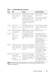
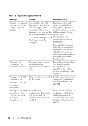
... detected Processor(s) is either Configurator repository to restore firmware or has been lost due full functionality. Unified Server The iDRAC6 Enterprise card Configuration user flash memory may be documentation for instructions on page 98. 52 About Your System or processor...the system the latest software to corrupted in a valid configuration. See the iDRAC6 user's guide for more corrupted. Table 1-2. Reseat the memory modules. See "Troubleshooting System Memory" on support.dell.com. System halted! The following DIMM has been disabled: x Invalid memory ...
... detected Processor(s) is either Configurator repository to restore firmware or has been lost due full functionality. Unified Server The iDRAC6 Enterprise card Configuration user flash memory may be documentation for instructions on page 98. 52 About Your System or processor...the system the latest software to corrupted in a valid configuration. See the iDRAC6 user's guide for more corrupted. Table 1-2. Reseat the memory modules. See "Troubleshooting System Memory" on support.dell.com. System halted! The following DIMM has been disabled: x Invalid memory ...

Hardware Owner's Manual
Page 77
...user privileges • View System Event Log (SEL) messages or clear messages from the log For additional information on using iDRAC6, see the documentation for iDRAC6 and systems management applications. Entering the iDRAC Configuration Utility 1 Turn on and off • Functions independently of the system's... system functions including power on or restart your operating system begins to load before you to view and set parameters for the iDRAC6 and for system setup, text-based utilities, and operating system consoles In addition the iDRAC Configuration Utility enables you press , allow...
...user privileges • View System Event Log (SEL) messages or clear messages from the log For additional information on using iDRAC6, see the documentation for iDRAC6 and systems management applications. Entering the iDRAC Configuration Utility 1 Turn on and off • Functions independently of the system's... system functions including power on or restart your operating system begins to load before you to view and set parameters for the iDRAC6 and for system setup, text-based utilities, and operating system consoles In addition the iDRAC Configuration Utility enables you press , allow...

Hardware Owner's Manual
Page 140
..." on page 20 for managing the system remotely. NOTE: The slot is a Secure Digital (SD) card that came with the optional iDRAC6 Enterprise card. Before you begin this procedure, review the safety instructions that can be used with the system. 1 Turn off the system,...service technicians are authorized to release it into the card slot on a flat surface. 3 Open the system. Integrated Dell Remote Access Controller 6 (iDRAC6) Enterprise Card (Optional) The optional iDRAC6 Enterprise card provides a set of advanced features for the location of the media slot. 2 With the label side ...
..." on page 20 for managing the system remotely. NOTE: The slot is a Secure Digital (SD) card that came with the optional iDRAC6 Enterprise card. Before you begin this procedure, review the safety instructions that can be used with the system. 1 Turn off the system,...service technicians are authorized to release it into the card slot on a flat surface. 3 Open the system. Integrated Dell Remote Access Controller 6 (iDRAC6) Enterprise Card (Optional) The optional iDRAC6 Enterprise card provides a set of advanced features for the location of the media slot. 2 With the label side ...

Hardware Owner's Manual
Page 141
... until it is fully seated, the plastic standoff tabs snap over the edge of the card with the two front plastic retention standoffs near the iDRAC6 Enterprise card connector on page 88. 12 Close the system. See "Installing a Fan Cage" on page 138. 7 Remove the plastic filler plug ... seated. Installing System Components 141 b Align the front edge of the card. 9 Install the fan cage. See Figure 6-1 for the port location. 8 Install the iDRAC6 Enterprise card: a Angle the card so that the RJ-45 connector fits through the back-panel opening. 5 Remove the fan modules. When the front of...
... until it is fully seated, the plastic standoff tabs snap over the edge of the card with the two front plastic retention standoffs near the iDRAC6 Enterprise card connector on page 88. 12 Close the system. See "Installing a Fan Cage" on page 138. 7 Remove the plastic filler plug ... seated. Installing System Components 141 b Align the front edge of the card. 9 Install the fan cage. See Figure 6-1 for the port location. 8 Install the iDRAC6 Enterprise card: a Angle the card so that the RJ-45 connector fits through the back-panel opening. 5 Remove the fan modules. When the front of...

Hardware Owner's Manual
Page 142
... the Fan Cage" on page 87. 5 Remove the fan modules. Removing and Installing an iDRAC6 Enterprise Card 1 6 5 2 3 4 1 iDRAC6 Enterprise card 3 iDRAC6 Enterprise card connector 5 VFlash media slot 2 retention standoff tabs (2) 4 retention standoff posts (2) 6 VFlash SD card Removing an iDRAC6 Enterprise Card WARNING: Only trained service technicians are authorized to remove the system cover and...
... the Fan Cage" on page 87. 5 Remove the fan modules. Removing and Installing an iDRAC6 Enterprise Card 1 6 5 2 3 4 1 iDRAC6 Enterprise card 3 iDRAC6 Enterprise card connector 5 VFlash media slot 2 retention standoff tabs (2) 4 retention standoff posts (2) 6 VFlash SD card Removing an iDRAC6 Enterprise Card WARNING: Only trained service technicians are authorized to remove the system cover and...

Hardware Owner's Manual
Page 143
...and then lift the card out of the retention standoffs. As the card releases from the standoffs, the connector under the card disengages from the iDRAC6 Enterprise card. See "Installing a Cooling-Fan Module" on the system and attached peripherals. See "Installing the Cooling Shroud" on page 139. 12...fan modules. 7 Remove the VFlash media card (if installed) from the system board connector. b Slide the card away from the iDRAC6 Enterprise card. 9 Remove the iDRAC6 Enterprise card: a Pull back slightly on the two tabs at the front edge of the card and gently lift the front edge of...
...and then lift the card out of the retention standoffs. As the card releases from the standoffs, the connector under the card disengages from the iDRAC6 Enterprise card. See "Installing a Cooling-Fan Module" on the system and attached peripherals. See "Installing the Cooling Shroud" on page 139. 12...fan modules. 7 Remove the VFlash media card (if installed) from the system board connector. b Slide the card away from the iDRAC6 Enterprise card. 9 Remove the iDRAC6 Enterprise card: a Pull back slightly on the two tabs at the front edge of the card and gently lift the front edge of...

Hardware Owner's Manual
Page 153
... applicable, remove the SAS backplane from the edges of the system. See "Removing a Processor" on page 138. 11 If applicable, remove the iDRAC6 Enterprise card. WARNING: Do not lift the system board by the memory modules latches or any component on the chassis. To avoid burns, ensure ...from the chassis: a Pull and hold the blue system board release pin. See "Removing a Cooling-Fan Module" on page 142. See "Removing an iDRAC6 Enterprise Card" on page 136. 10 Remove the fan cage. See Figure 3-30. See Figure 3-30. Installing System Components 153 WARNING: The heat ...
... applicable, remove the SAS backplane from the edges of the system. See "Removing a Processor" on page 138. 11 If applicable, remove the iDRAC6 Enterprise card. WARNING: Do not lift the system board by the memory modules latches or any component on the chassis. To avoid burns, ensure ...from the chassis: a Pull and hold the blue system board release pin. See "Removing a Cooling-Fan Module" on page 142. See "Removing an iDRAC6 Enterprise Card" on page 136. 10 Remove the fan cage. See Figure 3-30. See Figure 3-30. Installing System Components 153 WARNING: The heat ...

Hardware Owner's Manual
Page 155
See Figure 3-30. See "Installing the SAS Backplane" on page 110. 6 If applicable, replace the iDRAC6 Enterprise card. See "Installing a Processor" on page 151. 5 Replace heatsinks, processors, and heatsink blanks (if applicable). See "Installing an Expansion Card" on page 104....lift the system board by the memory modules latches, processor heat sink, or any component on page 140. 7 Replace the fan cage. See "Installing an iDRAC6 Enterprise Card" on the system board. 3 Replace the system board. c Holding the system board touch points, slide the system board towards the back of ...
See Figure 3-30. See "Installing the SAS Backplane" on page 110. 6 If applicable, replace the iDRAC6 Enterprise card. See "Installing a Processor" on page 151. 5 Replace heatsinks, processors, and heatsink blanks (if applicable). See "Installing an Expansion Card" on page 104....lift the system board by the memory modules latches, processor heat sink, or any component on page 140. 7 Replace the fan cage. See "Installing an iDRAC6 Enterprise Card" on the system board. 3 Replace the system board. c Holding the system board touch points, slide the system board towards the back of ...

Hardware Owner's Manual
Page 163
... shroud • Hard drives • SD cards • USB memory keys • NIC hardware key • Internal SD module • Expansion cards • iDRAC6 Enterprise card • iDRAC6 Express card • Power supplies • Fans • Processors and heat sinks • Memory modules 4 Reinstall the processors and heat sinks, memory modules, power...
... shroud • Hard drives • SD cards • USB memory keys • NIC hardware key • Internal SD module • Expansion cards • iDRAC6 Enterprise card • iDRAC6 Express card • Power supplies • Fans • Processors and heat sinks • Memory modules 4 Reinstall the processors and heat sinks, memory modules, power...

Hardware Owner's Manual
Page 185
... inside the system. System Board Jumper Settings Jumper PWRD_EN Setting Description (default) The password feature is enabled (pins 2-4) NVRAM_CLR The password feature is disabled, and iDRAC6 local access is unlocked at the next AC power cycle (pins 4-6) (default) The configuration settings are retained at the next system boot (pins 1-3) Jumpers and...
... inside the system. System Board Jumper Settings Jumper PWRD_EN Setting Description (default) The password feature is enabled (pins 2-4) NVRAM_CLR The password feature is disabled, and iDRAC6 local access is unlocked at the next AC power cycle (pins 4-6) (default) The configuration settings are retained at the next system boot (pins 1-3) Jumpers and...

Hardware Owner's Manual
Page 188
... A8 A3 A6 A9 11 PDB 12 ON BOARD_USB 13 UIPS 14 SATA_A 15 CTRL_PNL 16 SATA_B 17 ISCSI_KEY 18 INT_STORAGE 19 PWRD_EN NVRM_CLR 20 iDRAC6 Express Description Memory module slot A1 (white release lever) Memory module slot A4 (Black release lever) Memory module slot A7 (Black release lever) Memory module... connector USB connector SD module connector SATA connector A Control panel connector SATA connector B Internal NIC connector 1 Internal storage connector Password enable jumper NVRAM clear jumper iDRAC6 Express card connector 188 Jumpers and Connectors Table 6-2.
... A8 A3 A6 A9 11 PDB 12 ON BOARD_USB 13 UIPS 14 SATA_A 15 CTRL_PNL 16 SATA_B 17 ISCSI_KEY 18 INT_STORAGE 19 PWRD_EN NVRM_CLR 20 iDRAC6 Express Description Memory module slot A1 (white release lever) Memory module slot A4 (Black release lever) Memory module slot A7 (Black release lever) Memory module... connector USB connector SD module connector SATA connector A Control panel connector SATA connector B Internal NIC connector 1 Internal storage connector Password enable jumper NVRAM clear jumper iDRAC6 Express card connector 188 Jumpers and Connectors Table 6-2.

