Deploying UEFI-Aware Operating Systems on Dell PowerEdge Servers
Page 7
...is set to UEFI the BIOS Setup Utility fields, Boot Sequence and USB Flash Drive Emulation Type are automatically added and removed based in the \EFI\BOOT directory. In UEFI boot mode, it replaces both the BIOS Boot Manager and the boot configuration options in the UEFI Boot Manager...Data can be deleted. Boot options that were manually and operating system installed and can be entered. Boot Option entries for example, a hard‐disk drive has been removed), the option will continue to be listed, but will be renamed to BOOTx64.EFI (case insensitive) and placed in ...
...is set to UEFI the BIOS Setup Utility fields, Boot Sequence and USB Flash Drive Emulation Type are automatically added and removed based in the \EFI\BOOT directory. In UEFI boot mode, it replaces both the BIOS Boot Manager and the boot configuration options in the UEFI Boot Manager...Data can be deleted. Boot options that were manually and operating system installed and can be entered. Boot Option entries for example, a hard‐disk drive has been removed), the option will continue to be listed, but will be renamed to BOOTx64.EFI (case insensitive) and placed in ...

Hardware Owner's Manual
Page 32
...is missing or Reseat the cable. problem persists, replace connection. If the failure. See "Installing Memory Modules" on page 104 or "Troubleshooting System Memory" on page 174. See "Troubleshooting a Hard Drive" on page 167. 32 About Your System ...cable. LCD Status Messages (continued) Code Text Causes Corrective Actions E1810 Hard drive ## The specified hard drive fault. If the problem persists, replace cable. Check has been removed from drive. E1812 Hard drive ## The specified hard drive removed. Review has experienced a fault. & clear SEL. Information only...
...is missing or Reseat the cable. problem persists, replace connection. If the failure. See "Installing Memory Modules" on page 104 or "Troubleshooting System Memory" on page 174. See "Troubleshooting a Hard Drive" on page 167. 32 About Your System ...cable. LCD Status Messages (continued) Code Text Causes Corrective Actions E1810 Hard drive ## The specified hard drive fault. If the problem persists, replace cable. Check has been removed from drive. E1812 Hard drive ## The specified hard drive removed. Review has experienced a fault. & clear SEL. Information only...

Hardware Owner's Manual
Page 48
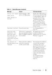
...Port x There is are installed in a valid configuration. device not found The operating system cannot Replace the optical medium, read from the hard drive, USB medium, or USB optical drive, or USB device, device. Quad rank DIMM detected after single rank or dual rank DIMM in...48 About Your System Table 1-2. Invalid memory configuration. "Troubleshooting a USB Device" on page 160, "Troubleshooting an Optical Drive" on page 171, or "Troubleshooting a Hard Drive" on page 179. Ensure that the USB the system could not find a cables, SAS/SATA backplane particular sector on...
...Port x There is are installed in a valid configuration. device not found The operating system cannot Replace the optical medium, read from the hard drive, USB medium, or USB optical drive, or USB device, device. Quad rank DIMM detected after single rank or dual rank DIMM in...48 About Your System Table 1-2. Invalid memory configuration. "Troubleshooting a USB Device" on page 160, "Troubleshooting an Optical Drive" on page 171, or "Troubleshooting a Hard Drive" on page 179. Ensure that the USB the system could not find a cables, SAS/SATA backplane particular sector on...
Hardware Owner's Manual
Page 49
...check the SEL to determine if single-bit or multi-bit errors were detected and replace the faulty memory module. System Messages (continued) Message Causes Corrective Actions Sector not found Faulty hard drive, USB Seek error device, or USB medium. Ensure that the USB or SAS backplane... cables are properly connected. See "Troubleshooting a USB Device" on page 160 or "Troubleshooting a Hard Drive" on page 193. For sparing mode, matched sets of Memory has been added or system memory has removed or a memory changed module may...
...check the SEL to determine if single-bit or multi-bit errors were detected and replace the faulty memory module. System Messages (continued) Message Causes Corrective Actions Sector not found Faulty hard drive, USB Seek error device, or USB medium. Ensure that the USB or SAS backplane... cables are properly connected. See "Troubleshooting a USB Device" on page 160 or "Troubleshooting a Hard Drive" on page 193. For sparing mode, matched sets of Memory has been added or system memory has removed or a memory changed module may...

Hardware Owner's Manual
Page 55
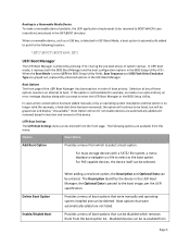
... memory configuration is : Invalid memory configuration. See "General Memory Module Installation Guidelines" on selected drive Faulty USB device, USB Replace the USB medium or medium, optical drive device. Warning Messages A warning message alerts you to a possible problem and prompts you to... Device" on page 160, "Troubleshooting an Optical Drive" on page 171, and "Troubleshooting a Hard Drive" on page 195. About Your System 55 If the problem persists, see the documentation that the USB, assembly, hard drive, or hard- Warning messages usually interrupt the task and require ...
... memory configuration is : Invalid memory configuration. See "General Memory Module Installation Guidelines" on selected drive Faulty USB device, USB Replace the USB medium or medium, optical drive device. Warning Messages A warning message alerts you to a possible problem and prompts you to... Device" on page 160, "Troubleshooting an Optical Drive" on page 171, and "Troubleshooting a Hard Drive" on page 195. About Your System 55 If the problem persists, see the documentation that the USB, assembly, hard drive, or hard- Warning messages usually interrupt the task and require ...

Hardware Owner's Manual
Page 92
.... Figure 3-7. c Close the handle to lock the drive in place. 4 Replace the front bezel. Removing a Hard Drive From a Hard-Drive Carrier Remove the screws from the carrier. Installing a Hot-Swap Hard Drive 1 2 1 release button 2 hard drive carrier handle 3 Install the hot-swap hard drive. See "Installing the Front Bezel" on the hard-drive carrier and separate the hard drive from the slide rails on page 85...
.... Figure 3-7. c Close the handle to lock the drive in place. 4 Replace the front bezel. Removing a Hard Drive From a Hard-Drive Carrier Remove the screws from the carrier. Installing a Hot-Swap Hard Drive 1 2 1 release button 2 hard drive carrier handle 3 Install the hot-swap hard drive. See "Installing the Front Bezel" on the hard-drive carrier and separate the hard drive from the slide rails on page 85...

Hardware Owner's Manual
Page 151
...• SAS B cable (available only with the tabs on the SAS backplane with 3.5-inch SAS backplane) • hard drive activity indicator cable • backplane power cable 5 Replace all the hard drives. See Figure 3-29. 3 Reconnect the cables that came with the system. 1 Align the slots on the chassis. ...System" on page 86. 8 Place the system upright and on its feet on page 91. 6 Replace the cooling shroud. Installing System Components 151 See "Installing a Hot-Swap Hard Drive" on a flat, stable surface. 9 Rotate the system feet outward 10 Install the Front Bezel. Installing...
...• SAS B cable (available only with the tabs on the SAS backplane with 3.5-inch SAS backplane) • hard drive activity indicator cable • backplane power cable 5 Replace all the hard drives. See Figure 3-29. 3 Reconnect the cables that came with the system. 1 Align the slots on the chassis. ...System" on page 86. 8 Place the system upright and on its feet on page 91. 6 Replace the cooling shroud. Installing System Components 151 See "Installing a Hot-Swap Hard Drive" on a flat, stable surface. 9 Rotate the system feet outward 10 Install the Front Bezel. Installing...

Hardware Owner's Manual
Page 152
...the system board. To avoid burns, ensure that came with an encryption program, you may be prompted to cool before you restart your hard drive(s). Be sure to create and safely store this procedure, review the safety instructions that the system has sufficient time to create a recovery ... surface. 4 Open the system. If you ever need to remove the system cover and access any attached cables. Before you are authorized to replace the system board, you must supply the recovery key when you can get hot during system or program setup. See "Removing an Expansion Card...
...the system board. To avoid burns, ensure that came with an encryption program, you may be prompted to cool before you restart your hard drive(s). Be sure to create and safely store this procedure, review the safety instructions that the system has sufficient time to create a recovery ... surface. 4 Open the system. If you ever need to remove the system cover and access any attached cables. Before you are authorized to replace the system board, you must supply the recovery key when you can get hot during system or program setup. See "Removing an Expansion Card...

Hardware Owner's Manual
Page 164
... System" on page 79. • Expansion cards • Power supplies • Fans • Processors and heat sinks • Memory modules • Hard-drive carriers 4 Ensure that all cables are properly connected. 5 Replace the cooling shroud. See "Installing System Components" on page 85. 2 Remove the cooling shroud. See "Installing the Cooling Shroud" on page...
... System" on page 79. • Expansion cards • Power supplies • Fans • Processors and heat sinks • Memory modules • Hard-drive carriers 4 Ensure that all cables are properly connected. 5 Replace the cooling shroud. See "Installing System Components" on page 85. 2 Remove the cooling shroud. See "Installing the Cooling Shroud" on page...

Hardware Owner's Manual
Page 205
... removing, 127 battery (system) replacing, 144 blank hard drive, 90-91 power supply, 83 C CD drive troubleshooting, 171 connectors USB, 20 video, 20 contacting Dell, 193 control panel assembly features, 12 installing, 148 LCD panel features, 14 removing, 145 cooling fans removing, 136 troubleshooting, 166 D damaged systems troubleshooting, 164 Dell contacting, 193 Dell PowerEdge Diagnostics using, 181 diagnostics...
... removing, 127 battery (system) replacing, 144 blank hard drive, 90-91 power supply, 83 C CD drive troubleshooting, 171 connectors USB, 20 video, 20 contacting Dell, 193 control panel assembly features, 12 installing, 148 LCD panel features, 14 removing, 145 cooling fans removing, 136 troubleshooting, 166 D damaged systems troubleshooting, 164 Dell contacting, 193 Dell PowerEdge Diagnostics using, 181 diagnostics...
Hardware Owner's Manual
Page 208
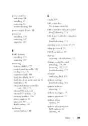
... 176 securing your system, 67, 73 setup password, 75 SSD hard drives, 89 startup accessing system features, 11 storage controller card installing, 134-135 removing, 132, 135 troubleshooting, 175 support contacting Dell, 193 system cooling troubleshooting, 166 system features accessing, 11 system ... 136 expansion cards, 118 hard drive blank, 90-91 hard drive from a drive carrier, 92 hard drives, 90 integrated storage controller card, 132, 135 internal SD card, 122 internal SD module, 121 memory modules, 106 power supplies, 82 processor, 107 RAID battery, 127 replacing system battery, 144 S ...
... 176 securing your system, 67, 73 setup password, 75 SSD hard drives, 89 startup accessing system features, 11 storage controller card installing, 134-135 removing, 132, 135 troubleshooting, 175 support contacting Dell, 193 system cooling troubleshooting, 166 system features accessing, 11 system ... 136 expansion cards, 118 hard drive blank, 90-91 hard drive from a drive carrier, 92 hard drives, 90 integrated storage controller card, 132, 135 internal SD card, 122 internal SD module, 121 memory modules, 106 power supplies, 82 processor, 107 RAID battery, 127 replacing system battery, 144 S ...


