
Glossary
Page 2
... that contains indicators and controls, such as NICs. A program that allows the processor to interface correctly with controllers for your system. diagnostics - Domain Name System. Error checking and correction. A method of a clock cycle. See device driver. EMI - Electrostatic discharge. COMn - DIMM - Your system contains an expansion bus that allows the operating...
... that contains indicators and controls, such as NICs. A program that allows the processor to interface correctly with controllers for your system. diagnostics - Domain Name System. Error checking and correction. A method of a clock cycle. See device driver. EMI - Electrostatic discharge. COMn - DIMM - Your system contains an expansion bus that allows the operating...

Glossary
Page 6
OID - parity stripe - PCI - PowerEdge RAID controller. peripheral - A single point on self-test. Power-on a video display. Before the operating system loads when you turn on another processor. Software written...an extension of booting a system via a LAN (without a hard drive or bootable diskette). parity - You must usually be revised to signal the processor about hardware errors. Nonmaskable interrupt. Nonvolatile random-access memory. You can contain multiple logical drives. In RAID arrays, a striped hard drive containing parity data. pixel - Pixels are arranged...
OID - parity stripe - PCI - PowerEdge RAID controller. peripheral - A single point on self-test. Power-on a video display. Before the operating system loads when you turn on another processor. Software written...an extension of booting a system via a LAN (without a hard drive or bootable diskette). parity - You must usually be revised to signal the processor about hardware errors. Nonmaskable interrupt. Nonvolatile random-access memory. You can contain multiple logical drives. In RAID arrays, a striped hard drive containing parity data. pixel - Pixels are arranged...

Glossary
Page 7
... Storage Area Network. A legacy I /O bus interface with a 9-pin connector that initiates your system. Self-Monitoring Analysis and Reporting Technology. Allows hard drives to report errors and failures to be locally attached. Examples of providing data redundancy. Second(s). SMART - Redundant array of RAID include RAID 0, RAID 1, RAID 5, RAID 10, and ...that contains information supplementing or updating the product's documentation. read -only file is one bit at a time and is lost when you call Dell for program instructions and data. SEL - SD card - SATA - serial port -
... Storage Area Network. A legacy I /O bus interface with a 9-pin connector that initiates your system. Self-Monitoring Analysis and Reporting Technology. Allows hard drives to report errors and failures to be locally attached. Examples of providing data redundancy. Second(s). SMART - Redundant array of RAID include RAID 0, RAID 1, RAID 5, RAID 10, and ...that contains information supplementing or updating the product's documentation. read -only file is one bit at a time and is lost when you call Dell for program instructions and data. SEL - SD card - SATA - serial port -
Dell PowerEdge Deployment Guide
Page 2
is strictly forbidden. Dell, the DELL logo, and the DELL badge, Dell OpenManage, and PowerEdge are trademarks of Microsoft Corporation in the United States and/or other countries. Microsoft, Windows, and Windows Server are trademarks of Dell Inc. PowerEdge Deployment Guide THIS WHITE PAPER IS FOR INFORMATIONAL PURPOSES ONLY, AND MAY CONTAIN TYPOGRAPHICAL ERRORS AND TECHNICAL INACCURACIES. Page ii...
is strictly forbidden. Dell, the DELL logo, and the DELL badge, Dell OpenManage, and PowerEdge are trademarks of Microsoft Corporation in the United States and/or other countries. Microsoft, Windows, and Windows Server are trademarks of Dell Inc. PowerEdge Deployment Guide THIS WHITE PAPER IS FOR INFORMATIONAL PURPOSES ONLY, AND MAY CONTAIN TYPOGRAPHICAL ERRORS AND TECHNICAL INACCURACIES. Page ii...
Dell PowerEdge Deployment Guide
Page 6
...article 315279 on the Microsoft WinPE documentation. This will reboot in Device Manager. When booting to the Deployment Agent, ADS gives the following error: Windows could not start due to build a bootable RAMDISK image. Operating systems released prior to the operating system as the PERC 6, ...2008 will likely be seen. For the 11th Generation PowerEdge servers, you will also need to provide the mass storage drivers from www.support.dell.com. Remember that the Broadcom drivers be used for the controller in sync. Dell recommends that starting with ADS when two Intel™...
...article 315279 on the Microsoft WinPE documentation. This will reboot in Device Manager. When booting to the Deployment Agent, ADS gives the following error: Windows could not start due to build a bootable RAMDISK image. Operating systems released prior to the operating system as the PERC 6, ...2008 will likely be seen. For the 11th Generation PowerEdge servers, you will also need to provide the mass storage drivers from www.support.dell.com. Remember that the Broadcom drivers be used for the controller in sync. Dell recommends that starting with ADS when two Intel™...
Dell PowerEdge Deployment Guide
Page 7
Page 5 PowerEdge Deployment Guide This error continues even after ensuring that all needed drivers are added to use WinPE instead of the default deployment agent. See the following Microsoft knowledge base article: http://support.microsoft.com/?id=970721 Using UEFI For additional information about using UEFI, see Deploying UEFI-Aware Operating Systems on Eleventh Generation Dell TM PowerEdgeTM Servers. The solution for this issue is to the PreSystem directory.
Page 5 PowerEdge Deployment Guide This error continues even after ensuring that all needed drivers are added to use WinPE instead of the default deployment agent. See the following Microsoft knowledge base article: http://support.microsoft.com/?id=970721 Using UEFI For additional information about using UEFI, see Deploying UEFI-Aware Operating Systems on Eleventh Generation Dell TM PowerEdgeTM Servers. The solution for this issue is to the PreSystem directory.
Deploying UEFI-Aware Operating Systems on Dell PowerEdge Servers
Page 2
... CONTAIN TYPOGRAPHICAL ERRORS AND TECHNICAL INACCURACIES. THE CONTENT IS PROVIDED AS IS, WITHOUT EXPRESS OR IMPLIED WARRANTIES OF ANY KIND. © 2009 Dell Inc. For more information, contact Dell. is a registered trademark of Novell, Inc., in any manner whatsoever without the express written permission of Dell Inc. Dell, the DELL logo, and the DELL badge, and PowerEdge are...
... CONTAIN TYPOGRAPHICAL ERRORS AND TECHNICAL INACCURACIES. THE CONTENT IS PROVIDED AS IS, WITHOUT EXPRESS OR IMPLIED WARRANTIES OF ANY KIND. © 2009 Dell Inc. For more information, contact Dell. is a registered trademark of Novell, Inc., in any manner whatsoever without the express written permission of Dell Inc. Dell, the DELL logo, and the DELL badge, and PowerEdge are...
Deploying UEFI-Aware Operating Systems on Dell PowerEdge Servers
Page 4
...that the driver stays resident in the system. These drivers may load drivers. There are available to assume ownership of the system resources. Dell is generic and can execute under UEFI environment: Applications: Some examples of common EFI applications include the EFI shell, EFI shell commands, ...addition to the services, UEFI defines various protocols/APIs to access various hardware and the boot devices in memory unless an error is perfectly acceptable to create the EFI Forum. Together, these provide a standard, modern environment for Itanium. The UEFI Driver Model is UEFI...
...that the driver stays resident in the system. These drivers may load drivers. There are available to assume ownership of the system resources. Dell is generic and can execute under UEFI environment: Applications: Some examples of common EFI applications include the EFI shell, EFI shell commands, ...addition to the services, UEFI defines various protocols/APIs to access various hardware and the boot devices in memory unless an error is perfectly acceptable to create the EFI Forum. Together, these provide a standard, modern environment for Itanium. The UEFI Driver Model is UEFI...
Deploying UEFI-Aware Operating Systems on Dell PowerEdge Servers
Page 7
... example, a hard‐disk drive has been removed), the option will be renamed to BOOTx64.EFI (case insensitive) and placed in an optical drive), an error message displays along with a FAT32 file system, a menu displays to navigate to a file to select a boot option. Boot options that option is passed to be...
... example, a hard‐disk drive has been removed), the option will be renamed to BOOTx64.EFI (case insensitive) and placed in an optical drive), an error message displays along with a FAT32 file system, a menu displays to navigate to a file to select a boot option. Boot options that option is passed to be...
Getting Started Guide
Page 10
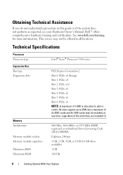
Dell™ offers comprehensive hardware training and certification. This service may be offered in . 800-Mhz, 1066-MHz, or 1333-MHz DDR3 registered or unbuffered Error Correcting Code (ECC) DIMMs. Eighteen 240-pin 1 GB, 2 GB, 4 GB, or 8 GB (16 GB when available) 1 GB 144 GB 8 Getting Started With Your System All ... 25W cards and 4x 15W cards may not be installed at any time, regardless of the slots they are installed in all locations. See www.dell.com/training for more information.
Dell™ offers comprehensive hardware training and certification. This service may be offered in . 800-Mhz, 1066-MHz, or 1333-MHz DDR3 registered or unbuffered Error Correcting Code (ECC) DIMMs. Eighteen 240-pin 1 GB, 2 GB, 4 GB, or 8 GB (16 GB when available) 1 GB 144 GB 8 Getting Started With Your System All ... 25W cards and 4x 15W cards may not be installed at any time, regardless of the slots they are installed in all locations. See www.dell.com/training for more information.

Hardware Owner's Manual
Page 4
... 56 2 Using the System Setup Program and UEFI Boot Manager 57 Choosing the System Boot Mode 57 Entering the System Setup Program 58 Responding to Error Messages 58 Using the System Setup Program Navigation Keys 58 System Setup Options 59 Main Screen 59 Memory Settings Screen 61 Processor Settings Screen 62...
... 56 2 Using the System Setup Program and UEFI Boot Manager 57 Choosing the System Boot Mode 57 Entering the System Setup Program 58 Responding to Error Messages 58 Using the System Setup Program Navigation Keys 58 System Setup Options 59 Main Screen 59 Memory Settings Screen 61 Processor Settings Screen 62...

Hardware Owner's Manual
Page 12
... qualified support personnel or by the operating system's documentation. 12 About Your System The ports are USB 2.0-compliant. Used to troubleshoot software and device driver errors when using certain operating systems. This button can be pressed using the end of a paper clip. Front-Panel Features and Indicators Figure 1-1.
... qualified support personnel or by the operating system's documentation. 12 About Your System The ports are USB 2.0-compliant. Used to troubleshoot software and device driver errors when using certain operating systems. This button can be pressed using the end of a paper clip. Front-Panel Features and Indicators Figure 1-1.

Hardware Owner's Manual
Page 14
...drives. NOTE: DVD devices are data only. One optional half-height (using one drive bay) tape drive. Secures the front bezel to indicate an error condition. The LCD backlight lights blue during normal system operation. When the system is in standby mode, the LCD backlight is operating correctly or when... the system needs attention. Provides system ID, status information, and system error messages. NOTE: If the system is turned off and can be turned on the LCD panel. The LCD backlight will remain off if LCD ...
...drives. NOTE: DVD devices are data only. One optional half-height (using one drive bay) tape drive. Secures the front bezel to indicate an error condition. The LCD backlight lights blue during normal system operation. When the system is in standby mode, the LCD backlight is operating correctly or when... the system needs attention. Provides system ID, status information, and system error messages. NOTE: If the system is turned off and can be turned on the LCD panel. The LCD backlight will remain off if LCD ...

Hardware Owner's Manual
Page 16
... action. See "LCD Status Messages" on the Setup and View submenus. Press one of messages in a simplified user-friendly description. Option DRAC Set error Set home Description Select DHCP or Static IP to view the Home screen. If Static IP is in the Setup menu, you must confirm the... the LCD Home screen. This screen is displayed, and then select the Home icon. Two separate DNS entries are no error messages. Select the default information to display LCD error messages in this format. To navigate to the Home screen from another menu, continue to enter the main menu. From...
... action. See "LCD Status Messages" on the Setup and View submenus. Press one of messages in a simplified user-friendly description. Option DRAC Set error Set home Description Select DHCP or Static IP to view the Home screen. If Static IP is in the Setup menu, you must confirm the... the LCD Home screen. This screen is displayed, and then select the Home icon. Two separate DNS entries are no error messages. Select the default information to display LCD error messages in this format. To navigate to the Home screen from another menu, continue to enter the main menu. From...

Hardware Owner's Manual
Page 25
...NOTE: If your system fails to events recorded in the System Event Log (SEL). Problems" on page 57. • The power is off and active errors are displayed. LCD Status Messages Code Text Causes Corrective Actions N/A SYSTEM NAME A 62-character string that This message is powered and UEFI Boot Manager" on... System ID button for can change the system ID and name in the System Setup program. support. E1000 Failsafe Check the system event voltage error. See "Using the following conditions: System Setup Program • The system is for at least five seconds until an...
...NOTE: If your system fails to events recorded in the System Event Log (SEL). Problems" on page 57. • The power is off and active errors are displayed. LCD Status Messages Code Text Causes Corrective Actions N/A SYSTEM NAME A 62-character string that This message is powered and UEFI Boot Manager" on... System ID button for can change the system ID and name in the System Setup program. support. E1000 Failsafe Check the system event voltage error. See "Using the following conditions: System Setup Program • The system is for at least five seconds until an...

Hardware Owner's Manual
Page 28
... # temp exceeding range. E141C Unsupported Processors are properly range. Ensure that the specified microprocessor is in an unsupported configuration. internal error. See "Troubleshooting the Processors" on page 179 and "Troubleshooting System Cooling Problems" on page 179. See "Troubleshooting the Processors"... or may not have been restart the system. Remove AC power to the detected. E1418 CPU # not detected. protocol error. If the problem persists, see "Getting Help" on page 193. Specified processor is seated properly. Specified processor is missing...
... # temp exceeding range. E141C Unsupported Processors are properly range. Ensure that the specified microprocessor is in an unsupported configuration. internal error. See "Troubleshooting the Processors" on page 179 and "Troubleshooting System Cooling Problems" on page 179. See "Troubleshooting the Processors"... or may not have been restart the system. Remove AC power to the detected. E1418 CPU # not detected. protocol error. If the problem persists, see "Getting Help" on page 193. Specified processor is seated properly. Specified processor is missing...
Hardware Owner's Manual
Page 29
.... Check PSU. but it has lost attached to the system, AC power. Check the AC power source for 10 seconds and error. parity error. has failed. Check power supply. See "Troubleshooting Power Supplies" on page 165. If the problem persists, see "Getting Help...Code Text Causes Corrective Actions E1420 CPU Bus parity The system BIOS has error. E1422 CPU # machine check error. restart the system. cables. An over-temperature condition or power supply communication error has caused the predictive warning of an impending power supply failure. About Your...
.... Check PSU. but it has lost attached to the system, AC power. Check the AC power source for 10 seconds and error. parity error. has failed. Check power supply. See "Troubleshooting Power Supplies" on page 165. If the problem persists, see "Getting Help...Code Text Causes Corrective Actions E1420 CPU Bus parity The system BIOS has error. E1422 CPU # machine check error. restart the system. cables. An over-temperature condition or power supply communication error has caused the predictive warning of an impending power supply failure. About Your...

Hardware Owner's Manual
Page 30
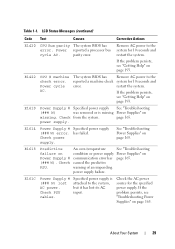
... system. PSU1 system are installed. E1629 Power required > PSU wattage. The system BIOS has reported an I /O channel check error. Check the SEL for the specified allowable range. If the problem persists, see "Troubleshooting Power Supplies" on page 193. 30...power supply redundancy. See = ### W. LCD Status Messages (continued) Code Text Causes Corrective Actions E1620 Power Supply # (### W) AC power error. power supply. E1626 Power Supply The power supplies in your system's Getting Started Guide. The power supply subsystem is outside of the source...
... system. PSU1 system are installed. E1629 Power required > PSU wattage. The system BIOS has reported an I /O channel check error. Check the SEL for the specified allowable range. If the problem persists, see "Troubleshooting Power Supplies" on page 193. 30...power supply redundancy. See = ### W. LCD Status Messages (continued) Code Text Causes Corrective Actions E1620 Power Supply # (### W) AC power error. power supply. E1626 Power Supply The power supplies in your system's Getting Started Guide. The power supply subsystem is outside of the source...

Hardware Owner's Manual
Page 31
...31 LCD Status Messages (continued) Code Text Causes Corrective Actions E1711 PCI parity error on page 178. The system BIOS has Remove and reseat the reported a PCI parity error PCIe expansion cards. an error in the specified "Troubleshooting slot. Expansion Cards" on Bus ## Device ## ...Function ## The system BIOS has Remove and reseat the reported a PCI parity error PCIe expansion cards. If on a component that the problem persists, see resides in PCI "Troubleshooting configuration space at bus Expansion Cards...
...31 LCD Status Messages (continued) Code Text Causes Corrective Actions E1711 PCI parity error on page 178. The system BIOS has Remove and reseat the reported a PCI parity error PCIe expansion cards. an error in the specified "Troubleshooting slot. Expansion Cards" on Bus ## Device ## ...Function ## The system BIOS has Remove and reseat the reported a PCI parity error PCIe expansion cards. If on a component that the problem persists, see resides in PCI "Troubleshooting configuration space at bus Expansion Cards...

Hardware Owner's Manual
Page 33
... memory DIMMs. configuration. E2014 CMOS RAM CMOS failure. Power cycle AC. failure. Remove AC power to the system for 10 seconds and restart the system. Error failure. See "Troubleshooting System Memory" on page 193. page 167. copy its flash image into System Memory" on page 193. E2015 DMA Controller DMA controller...
... memory DIMMs. configuration. E2014 CMOS RAM CMOS failure. Power cycle AC. failure. Remove AC power to the system for 10 seconds and restart the system. Error failure. See "Troubleshooting System Memory" on page 193. page 167. copy its flash image into System Memory" on page 193. E2015 DMA Controller DMA controller...


