
Tower-to-Rack Conversion Guide
Page 4
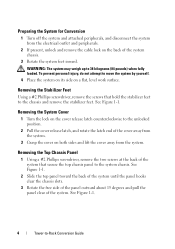
.... Removing the Stabilizer Feet Using a #2 Phillips screwdriver, remove the screws that secure the top chassis panel to the chassis and remove the stabilizer feet. WARNING: The system may weigh up to -Rack Conversion Guide Removing the System Cover 1 Turn the lock on the cover release latch counterclockwise to move... peripherals. 2 If present, unlock and remove the cable lock on the back of the system that hold the stabilizer feet to the system chassis. To prevent personal injury, do not attempt to the unlocked position. 2 Pull the cover release latch, and rotate the latch end of ...
.... Removing the Stabilizer Feet Using a #2 Phillips screwdriver, remove the screws that secure the top chassis panel to the chassis and remove the stabilizer feet. WARNING: The system may weigh up to -Rack Conversion Guide Removing the System Cover 1 Turn the lock on the cover release latch counterclockwise to move... peripherals. 2 If present, unlock and remove the cable lock on the back of the system that hold the stabilizer feet to the system chassis. To prevent personal injury, do not attempt to the unlocked position. 2 Pull the cover release latch, and rotate the latch end of ...
Tower-to-Rack Conversion Guide
Page 5
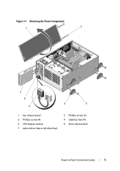
Figure 1-1. Removing the Tower Components 1 2 7 6 5 4 3 1 top chassis panel 3 Phillips screw (4) 5 LCD display module 7 optical drive (top or left drive bay) 2 Phillips screw (2) 4 stabilizer foot (4) 6 drive release latch Tower-to-Rack Conversion Guide 5
Figure 1-1. Removing the Tower Components 1 2 7 6 5 4 3 1 top chassis panel 3 Phillips screw (4) 5 LCD display module 7 optical drive (top or left drive bay) 2 Phillips screw (2) 4 stabilizer foot (4) 6 drive release latch Tower-to-Rack Conversion Guide 5
Tower-to-Rack Conversion Guide
Page 6
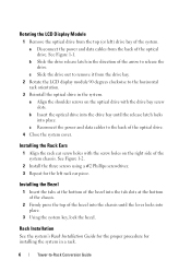
... drive bay of the arrow to -Rack Conversion Guide Installing the Rack Ears 1 Align the rack ear screw holes with the drive bay screw slots. Installing the Bezel 1 Insert the tabs at the bottom of the bezel into the tab slots at the bottom of the chassis. 2 Firmly press the top of... the system chassis. c Slide the drive out to remove it from the drive bay. 2 Rotate the LCD display module 90 degrees clockwise to the horizontal rack orientation. 3 Reinstall the optical drive in a rack. 6 Tower-to release the drive. b...
... drive bay of the arrow to -Rack Conversion Guide Installing the Rack Ears 1 Align the rack ear screw holes with the drive bay screw slots. Installing the Bezel 1 Insert the tabs at the bottom of the bezel into the tab slots at the bottom of the chassis. 2 Firmly press the top of... the system chassis. c Slide the drive out to remove it from the drive bay. 2 Rotate the LCD display module 90 degrees clockwise to the horizontal rack orientation. 3 Reinstall the optical drive in a rack. 6 Tower-to release the drive. b...
Hardware Owner's Manual
Page 88
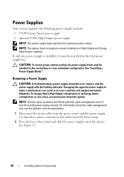
...Output power supply NOTE: The power supply label specifies the maximum power output. NOTE: The system does not support a mixed installation of the chassis. CAUTION: To ensure proper system cooling, the power supply blank must be installed in the first power supply bay. To change from a ...an error condition and unexpected system shutdown. See "Installing a Power Supply Blank." For information about the cable management arm, see the system's rack documentation. 1 Disconnect the power cable from the Velcro strap. 2 Press the lever release latch and slide the power supply out of High ...
...Output power supply NOTE: The power supply label specifies the maximum power output. NOTE: The system does not support a mixed installation of the chassis. CAUTION: To ensure proper system cooling, the power supply blank must be installed in the first power supply bay. To change from a ...an error condition and unexpected system shutdown. See "Installing a Power Supply Blank." For information about the cable management arm, see the system's rack documentation. 1 Disconnect the power cable from the Velcro strap. 2 Press the lever release latch and slide the power supply out of High ...
Hardware Owner's Manual
Page 89
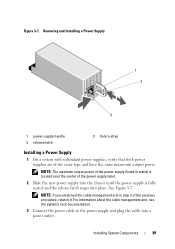
... unlatched the cable management arm in watts) is located near the center of the power supply label. 2 Slide the new power supply into the chassis until the power supply is fully seated and the release latch snaps into a power outlet. Figure 3-7. NOTE: The maximum output power of the... (listed in step 2 of the same type and have the same maximum output power. For information about the cable management arm, see the system's rack documentation. 3 Connect the power cable to the power supply and plug the cable into place. Installing System Components 89 See Figure 3-7. Removing and Installing...
... unlatched the cable management arm in watts) is located near the center of the power supply label. 2 Slide the new power supply into the chassis until the power supply is fully seated and the release latch snaps into a power outlet. Figure 3-7. NOTE: The maximum output power of the... (listed in step 2 of the same type and have the same maximum output power. For information about the cable management arm, see the system's rack documentation. 3 Connect the power cable to the power supply and plug the cable into place. Installing System Components 89 See Figure 3-7. Removing and Installing...
Hardware Owner's Manual
Page 152
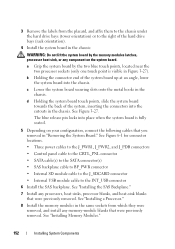
...any component on your configuration, connect the following cables that you removed in the same sockets from the placard, and affix them to the chassis under the hard drive bays (tower orientation) or to the INT_USB connector 6 Install the SAS backplane. c Lower the system board securing...3-27). See "Installing Memory Modules." 152 Installing System Components b Holding the connector end of the hard drive bays (rack orientation). 4 Install the system board in the chassis: WARNING: Do not lift the system board by the two blue touch points, located near the two processor sockets (only...
...any component on your configuration, connect the following cables that you removed in the same sockets from the placard, and affix them to the chassis under the hard drive bays (tower orientation) or to the INT_USB connector 6 Install the SAS backplane. c Lower the system board securing...3-27). See "Installing Memory Modules." 152 Installing System Components b Holding the connector end of the hard drive bays (rack orientation). 4 Install the system board in the chassis: WARNING: Do not lift the system board by the two blue touch points, located near the two processor sockets (only...


