
Hardware Owner's Manual
Page 47
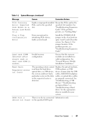
...detected after configuration. "Troubleshooting a USB Device", "Troubleshooting an Optical Drive", or "Troubleshooting a Hard Drive" for jumper location. persists, see "Troubleshooting Expansion Cards." Read ...slot number. See "General Memory Module Installation Guidelines." System Messages (continued) Message Causes Corrective Actions PCIe Training Faulty or improperly installed Reseat the PCIe card in the Error: Expected PCIe card in initializing PCIe device; device not found The operating system cannot Replace the optical medium, read from the hard drive...
...detected after configuration. "Troubleshooting a USB Device", "Troubleshooting an Optical Drive", or "Troubleshooting a Hard Drive" for jumper location. persists, see "Troubleshooting Expansion Cards." Read ...slot number. See "General Memory Module Installation Guidelines." System Messages (continued) Message Causes Corrective Actions PCIe Training Faulty or improperly installed Reseat the PCIe card in the Error: Expected PCIe card in initializing PCIe device; device not found The operating system cannot Replace the optical medium, read from the hard drive...
Hardware Owner's Manual
Page 63
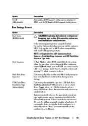
... CAUTION: Switching the boot mode could prevent the system from hard drives in the system during system startup. If Boot Mode is set to BIOS, this slot that is set to do so. Hard disk allows the USB flash drive to act as a removable diskette drive, you can access the UEFI boot manager utility by rebooting...
... CAUTION: Switching the boot mode could prevent the system from hard drives in the system during system startup. If Boot Mode is set to BIOS, this slot that is set to do so. Hard disk allows the USB flash drive to act as a removable diskette drive, you can access the UEFI boot manager utility by rebooting...
Hardware Owner's Manual
Page 79
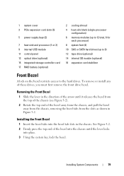
...slots (5) 5 power supply bays (2) 7 heat sink and processor (1 or 2) 9 internal USB module 11 control panel 13 optical drive (optional) 15 integrated storage controller card 17 RAID battery (optional) 2 cooling shroud 4 heat sink blank (single-processor configuration) 6 memory modules (up to 12 total, 6 for each processor) 8 system feet (4) 10 SAS or SATA hard drives... (up to 8) 12 tape drive (optional) 14 internal SD module (optional) 16 expansion card stabilizer Front Bezel A lock on the bezel restricts...
...slots (5) 5 power supply bays (2) 7 heat sink and processor (1 or 2) 9 internal USB module 11 control panel 13 optical drive (optional) 15 integrated storage controller card 17 RAID battery (optional) 2 cooling shroud 4 heat sink blank (single-processor configuration) 6 memory modules (up to 12 total, 6 for each processor) 8 system feet (4) 10 SAS or SATA hard drives... (up to 8) 12 tape drive (optional) 14 internal SD module (optional) 16 expansion card stabilizer Front Bezel A lock on the bezel restricts...
Hardware Owner's Manual
Page 80
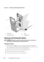
... a hard drive or power supply, turn off the system and attached peripherals, and disconnect the system from the electrical outlet and peripherals. 2 Remove the front bezel. Opening the System 1 Unless you . See "Removing the Front Bezel." 3 Rotate the system feet inward. Removing and Installing the Front Bezel 2 1 3 1 front bezel 3 bezel tab slots (2) 4 2 lever...
... a hard drive or power supply, turn off the system and attached peripherals, and disconnect the system from the electrical outlet and peripherals. 2 Remove the front bezel. Opening the System 1 Unless you . See "Removing the Front Bezel." 3 Rotate the system feet inward. Removing and Installing the Front Bezel 2 1 3 1 front bezel 3 bezel tab slots (2) 4 2 lever...
Hardware Owner's Manual
Page 82
... system. 3 Reinstall the system cover: a Place the bottom edge of the cover, opposite from the cover release latch, into the slots in the system chassis. d Turn the cover latch release lock clockwise to the locked position. 4 Place the system upright and on ... the following configurations: • Eight 2.5-inch drive bays • Eight 3.5-inch drive bays All chassis support hot-swappable SAS and SATA hard drives, and the 2.5inch-bay chassis also supports hot-swappable SSD hard drives in the hard-drive bays. Doing so can cause a drive failure. 82 Installing System Components 2 Ensure that...
... system. 3 Reinstall the system cover: a Place the bottom edge of the cover, opposite from the cover release latch, into the slots in the system chassis. d Turn the cover latch release lock clockwise to the locked position. 4 Place the system upright and on ... the following configurations: • Eight 2.5-inch drive bays • Eight 3.5-inch drive bays All chassis support hot-swappable SAS and SATA hard drives, and the 2.5inch-bay chassis also supports hot-swappable SSD hard drives in the hard-drive bays. Doing so can cause a drive failure. 82 Installing System Components 2 Ensure that...
Hardware Owner's Manual
Page 83
... be installed in size and must have been tested and approved for the formatting to six SATA drives may be installed in hard-drive slots 0 and 1 only. See "Removing the Front Bezel." 2 Grasp the front of the hard-drive blank, press the release lever on the right side, and slide the blank out until it is...
... be installed in size and must have been tested and approved for the formatting to six SATA drives may be installed in hard-drive slots 0 and 1 only. See "Removing the Front Bezel." 2 Grasp the front of the hard-drive blank, press the release lever on the right side, and slide the blank out until it is...
Hardware Owner's Manual
Page 112
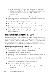
...flat, stable surface. 16 Reattach any attached peripherals, and disconnect the system from the storage-card slot. Integrated Storage Controller Card Your system includes a dedicated slot on the system board for an integrated storage controller card that provides the storage subsystem for your ... attached peripherals. 18 (Optional) Test the drive by the version of the storage controller included with your system's internal hard drives. The controller supports SAS and SATA hard drives and also enables you are installing a SCSI tape drive, connect the SCSI interface cable in RAID ...
...flat, stable surface. 16 Reattach any attached peripherals, and disconnect the system from the storage-card slot. Integrated Storage Controller Card Your system includes a dedicated slot on the system board for an integrated storage controller card that provides the storage subsystem for your ... attached peripherals. 18 (Optional) Test the drive by the version of the storage controller included with your system's internal hard drives. The controller supports SAS and SATA hard drives and also enables you are installing a SCSI tape drive, connect the SCSI interface cable in RAID ...
Hardware Owner's Manual
Page 144
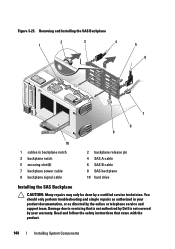
... not authorized by Dell is not covered by the online or telephone service and support team. You should only perform troubleshooting and simple repairs as authorized in backplane notch 3 backplane notch 5 securing slot (8) 7 backplane power cable 9 backplane signal cable 2 backplane release pin 4 SAS A cable 6 SAS B cable 8 SAS backplane 10 hard drive Installing the SAS...
... not authorized by Dell is not covered by the online or telephone service and support team. You should only perform troubleshooting and simple repairs as authorized in backplane notch 3 backplane notch 5 securing slot (8) 7 backplane power cable 9 backplane signal cable 2 backplane release pin 4 SAS A cable 6 SAS B cable 8 SAS backplane 10 hard drive Installing the SAS...
Hardware Owner's Manual
Page 145
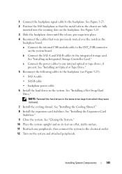
...and on its feet on the system and attached peripherals. See "Installing the Expansion Card Stabilizer." 9 Close the system. NOTE: Reinstall the hard drives in the backplane board. See "Installing the Cooling Shroud." 8 Install the expansion card stabilizer. See Figure 3-25. 3 Slide the backplane... down until the release pin snaps into the securing slots on the system board. Installing System Components 145 c Connect the power cables to any peripherals, then connect the system to the electrical ...
...and on its feet on the system and attached peripherals. See "Installing the Expansion Card Stabilizer." 9 Close the system. NOTE: Reinstall the hard drives in the backplane board. See "Installing the Cooling Shroud." 8 Install the expansion card stabilizer. See Figure 3-25. 3 Slide the backplane... down until the release pin snaps into the securing slots on the system board. Installing System Components 145 c Connect the power cables to any peripherals, then connect the system to the electrical ...
Hardware Owner's Manual
Page 152
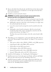
...back of the system, inserting the connectors into the cutouts in the same sockets from the placard, and affix them to the chassis under the hard drive bays (tower orientation) or to the INT_USB connector 6 Install the SAS backplane. See "Installing the SAS Backplane." 7 Install any processors, heat... near the two processor sockets (only one touch point is fully seated. 5 Depending on the system board. c Lower the system board securing slots onto the metal hooks in Figure 3-27). 3 Remove the labels from which they were removed, and install any memory-module blanks that were ...
...back of the system, inserting the connectors into the cutouts in the same sockets from the placard, and affix them to the chassis under the hard drive bays (tower orientation) or to the INT_USB connector 6 Install the SAS backplane. See "Installing the SAS Backplane." 7 Install any processors, heat... near the two processor sockets (only one touch point is fully seated. 5 Depending on the system board. c Lower the system board securing slots onto the metal hooks in Figure 3-27). 3 Remove the labels from which they were removed, and install any memory-module blanks that were ...


