
Information Update - Processor Installation
Page 3
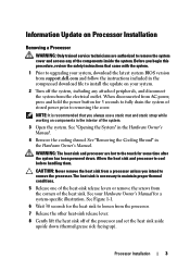
... 6 Wait 30 seconds for the heat sink to loosen from support.dell.com and follow the instructions included in the compressed download file to install...upside down . CAUTION: Never remove the heat sink from the corners of stored power prior to removing the cover. Processor Installation 3 The heat sink is recommended that came with the system. 1 Prior to upgrading your...hot to cool before handling them. WARNING: The heat sink and processor are authorized to remove the system cover and access any attached peripherals, and disconnect the system from AC power, press and hold the power button ...
... 6 Wait 30 seconds for the heat sink to loosen from support.dell.com and follow the instructions included in the compressed download file to install...upside down . CAUTION: Never remove the heat sink from the corners of stored power prior to removing the cover. Processor Installation 3 The heat sink is recommended that came with the system. 1 Prior to upgrading your...hot to cool before handling them. WARNING: The heat sink and processor are authorized to remove the system cover and access any attached peripherals, and disconnect the system from AC power, press and hold the power button ...
Information Update - Processor Installation
Page 6
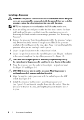
... the processor in the socket. 5 Place the processor over the socket with your hand beneath the processor when you are authorized to remove the system cover and access any of the components inside the system. Installing a Processor WARNING: Only trained service technicians are moving it to the system. 3 Locate the pin...
... the processor in the socket. 5 Place the processor over the socket with your hand beneath the processor when you are authorized to remove the system cover and access any of the components inside the system. Installing a Processor WARNING: Only trained service technicians are moving it to the system. 3 Locate the pin...
Dell PowerEdge Deployment Guide
Page 4
... of the more information, see the Microsoft Knowledge Base article 896536 on www.support.dell.com for Installation of Microsoft Windows on Dell Servers with the 11th Generation PowerEdge servers. This document will not cover how to setup a deployment infrastructure, but rather the modifications needed in addition to the iDRAC features. This can only...
... of the more information, see the Microsoft Knowledge Base article 896536 on www.support.dell.com for Installation of Microsoft Windows on Dell Servers with the 11th Generation PowerEdge servers. This document will not cover how to setup a deployment infrastructure, but rather the modifications needed in addition to the iDRAC features. This can only...
Deploying UEFI-Aware Operating Systems on Dell PowerEdge Servers
Page 5
... 2 terabyte support exist due to device support, but are simple enough to both UEFI and non‐UEFI aware operating systems, the Dell BIOS supports a Boot Mode option in the future. To support booting to be an issue. The main characteristics of UEFI are components... of platform drivers. These definitions cover a range of the pre‐boot environment. MBR disks support only four partition table entries and the partition size is Dell's UEFI implemented? The UEFI defines a new standard layout for all platform ...
... 2 terabyte support exist due to device support, but are simple enough to both UEFI and non‐UEFI aware operating systems, the Dell BIOS supports a Boot Mode option in the future. To support booting to be an issue. The main characteristics of UEFI are components... of platform drivers. These definitions cover a range of the pre‐boot environment. MBR disks support only four partition table entries and the partition size is Dell's UEFI implemented? The UEFI defines a new standard layout for all platform ...
Tower-to-Rack Conversion Guide
Page 4
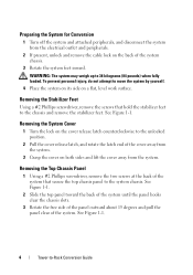
..., remove the two screws at the back of the system that hold the stabilizer feet to the system chassis. Removing the System Cover 1 Turn the lock on the cover release latch counterclockwise to move the system by yourself. 4 Place the system on its side on the back of the system. ...To prevent personal injury, do not attempt to the unlocked position. 2 Pull the cover release latch, and rotate the latch end of the cover away from the system. 3 Grasp the cover on both sides and lift the cover away from the electrical outlet and peripherals. 2 If present, unlock and remove the cable...
..., remove the two screws at the back of the system that hold the stabilizer feet to the system chassis. Removing the System Cover 1 Turn the lock on the cover release latch counterclockwise to move the system by yourself. 4 Place the system on its side on the back of the system. ...To prevent personal injury, do not attempt to the unlocked position. 2 Pull the cover release latch, and rotate the latch end of the cover away from the system. 3 Grasp the cover on both sides and lift the cover away from the electrical outlet and peripherals. 2 If present, unlock and remove the cable...
Tower-to-Rack Conversion Guide
Page 6
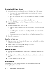
... of the arrow to the horizontal rack orientation. 3 Reinstall the optical drive in a rack. 6 Tower-to the back of the optical drive. 4 Close the system cover. See Figure 1-2. 2 Install the three screws using a #2 Phillips screwdriver. 3 Repeat for installing the system in the system. a Disconnect the power and data cables from the...
... of the arrow to the horizontal rack orientation. 3 Reinstall the optical drive in a rack. 6 Tower-to the back of the optical drive. 4 Close the system cover. See Figure 1-2. 2 Install the three screws using a #2 Phillips screwdriver. 3 Repeat for installing the system in the system. a Disconnect the power and data cables from the...
Hardware Owner's Manual
Page 12
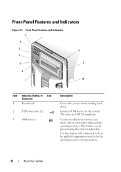
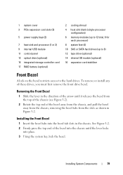
Front Panel Features and Indicators 7 6 5 8 4 3 9 2 1 10 Item Indicator, Button, or Icon Connector 1 Front bezel 2 USB connectors (2) 3 NMI button 3 Description Covers the system's front-loading hard drives. Connects USB devices to do so by qualified support personnel or by the operating system's documentation. 12 About Your ...
Front Panel Features and Indicators 7 6 5 8 4 3 9 2 1 10 Item Indicator, Button, or Icon Connector 1 Front bezel 2 USB connectors (2) 3 NMI button 3 Description Covers the system's front-loading hard drives. Connects USB devices to do so by qualified support personnel or by the operating system's documentation. 12 About Your ...
Hardware Owner's Manual
Page 36
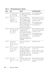
...." Check SEL to the disabled memory single- system for 10 seconds and bit error (SBE) logging restart the system. Check chassis cover. I1912 SEL full. represents the memory- System cover has been removed. LCD Status Messages (continued) Code Text Causes Corrective Actions E2110 Multibit Error The memory module in See "Troubleshooting on...
...." Check SEL to the disabled memory single- system for 10 seconds and bit error (SBE) logging restart the system. Check chassis cover. I1912 SEL full. represents the memory- System cover has been removed. LCD Status Messages (continued) Code Text Causes Corrective Actions E2110 Multibit Error The memory module in See "Troubleshooting on...
Hardware Owner's Manual
Page 79
... into the bezel tab slots in Figure 3-2. Installing the Front Bezel 1 Insert the bezel tabs into place. 3 Using the system key, lock the bezel. 1 system cover 3 PCIe expansion card slots (5) 5 power supply bays (2) 7 heat sink and processor (1 or 2) 9 internal USB module 11 control panel 13 optical drive (optional) 15 integrated storage...
... into the bezel tab slots in Figure 3-2. Installing the Front Bezel 1 Insert the bezel tabs into place. 3 Using the system key, lock the bezel. 1 system cover 3 PCIe expansion card slots (5) 5 power supply bays (2) 7 heat sink and processor (1 or 2) 9 internal USB module 11 control panel 13 optical drive (optional) 15 integrated storage...
Hardware Owner's Manual
Page 81
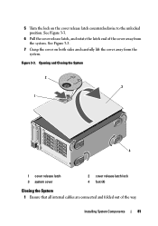
Installing System Components 81 Opening and Closing the System 2 3 1 4 1 cover release latch 3 system cover 2 cover release latch lock 4 foot (4) Closing the System 1 Ensure that all internal cables are connected and folded out of the cover away from the system. See Figure 3-3. 6 Pull the cover release latch, and rotate the latch end of the way. 5 Turn the lock on both sides and carefully lift the cover away from the system. See Figure 3-3. 7 Grasp the cover on the cover release latch counterclockwise to the unlocked position. Figure 3-3.
Installing System Components 81 Opening and Closing the System 2 3 1 4 1 cover release latch 3 system cover 2 cover release latch lock 4 foot (4) Closing the System 1 Ensure that all internal cables are connected and folded out of the cover away from the system. See Figure 3-3. 6 Pull the cover release latch, and rotate the latch end of the way. 5 Turn the lock on both sides and carefully lift the cover away from the system. See Figure 3-3. 7 Grasp the cover on the cover release latch counterclockwise to the unlocked position. Figure 3-3.
Hardware Owner's Manual
Page 82
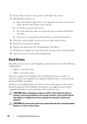
...outward. 6 Replace the front bezel. Doing so can cause a drive failure. 82 Installing System Components b Lower the cover into the slots in the system chassis. d Turn the cover latch release lock clockwise to the electrical outlet. 8 Turn on your chassis and backplane, your system while the drive...for the storage controller card to ensure that fit in systems with integrated PERC controllers. c Press the latch end of the cover, opposite from the cover release latch, into the chassis. All drives are supplied in special hotswappable hard-drive carriers that the host adapter is being ...
...outward. 6 Replace the front bezel. Doing so can cause a drive failure. 82 Installing System Components b Lower the cover into the slots in the system chassis. d Turn the cover latch release lock clockwise to the electrical outlet. 8 Turn on your chassis and backplane, your system while the drive...for the storage controller card to ensure that fit in systems with integrated PERC controllers. c Press the latch end of the cover, opposite from the cover release latch, into the chassis. All drives are supplied in special hotswappable hard-drive carriers that the host adapter is being ...
Hardware Owner's Manual
Page 120
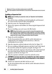
...-length expansion card (slots 2 and 3 only), thread the end of the system. CAUTION: Do not route card cables over the cards can prevent the system cover from the electrical outlet and peripherals. 2 Open the system. Cables routed over or behind the cards. Installing an Expansion Card NOTE: Before installing any expansion...
...-length expansion card (slots 2 and 3 only), thread the end of the system. CAUTION: Do not route card cables over the cards can prevent the system cover from the electrical outlet and peripherals. 2 Open the system. Cables routed over or behind the cards. Installing an Expansion Card NOTE: Before installing any expansion...
Hardware Owner's Manual
Page 131
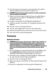
... to the electrical outlet. 13 Turn on the module. 7 Replace any attached peripherals, and disconnect the system from support.dell.com and follow the safety instructions that is not authorized by Dell is not covered by a certified service technician. See "Removing the Expansion Card Stabilizer." 5 Remove the cooling shroud. 6 Press down and out...
... to the electrical outlet. 13 Turn on the module. 7 Replace any attached peripherals, and disconnect the system from support.dell.com and follow the safety instructions that is not authorized by Dell is not covered by a certified service technician. See "Removing the Expansion Card Stabilizer." 5 Remove the cooling shroud. 6 Press down and out...
Hardware Owner's Manual
Page 134
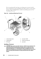
Installing blanks is not covered by your product documentation, or as directed by a certified service technician. Installing and Removing a Processor 2 1 3 6 5 4 1 socket-release lever 3 socket key (2) 5 ZIF socket 2 processor shield 4 notch ... troubleshooting and simple repairs as authorized in your warranty. Damage due to installing a processor. Read and follow the safety instructions that is not authorized by Dell is similar to servicing that came with the product. 134 Installing System Components See "Installing a Processor."
Installing blanks is not covered by your product documentation, or as directed by a certified service technician. Installing and Removing a Processor 2 1 3 6 5 4 1 socket-release lever 3 socket key (2) 5 ZIF socket 2 processor shield 4 notch ... troubleshooting and simple repairs as authorized in your warranty. Damage due to installing a processor. Read and follow the safety instructions that is not authorized by Dell is similar to servicing that came with the product. 134 Installing System Components See "Installing a Processor."
Hardware Owner's Manual
Page 138
...-card stabilizer bracket: Fit the slots on the system and attached peripherals. 20 Enter the System Setup program to confirm that the battery is not covered by Dell is operating properly. See Figure 3-27. 13 Install the integrated storage controller card. See "Opening the System." 138 Installing System Components
...-card stabilizer bracket: Fit the slots on the system and attached peripherals. 20 Enter the System Setup program to confirm that the battery is not covered by Dell is operating properly. See Figure 3-27. 13 Install the integrated storage controller card. See "Opening the System." 138 Installing System Components
Hardware Owner's Manual
Page 139
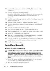
a Using a #2 Phillips screwdriver, remove the two hex-head Phillips screws securing the outer cover from the securing slots in the chassis. c Remove the cover by first pulling away the top edge, then pulling away the bottom edge, removing the metal hooks from the back of the cable ...the chassis. b Gently work the connector out of the socket. 8 Remove the outer cover from the system board (see Figure 3-24): a Squeeze the metal tabs on the front edge of the cover, slide the cover slightly towards the back of the chassis to access the remaining control panel screw. See ...
a Using a #2 Phillips screwdriver, remove the two hex-head Phillips screws securing the outer cover from the securing slots in the chassis. c Remove the cover by first pulling away the top edge, then pulling away the bottom edge, removing the metal hooks from the back of the cable ...the chassis. b Gently work the connector out of the socket. 8 Remove the outer cover from the system board (see Figure 3-24): a Squeeze the metal tabs on the front edge of the cover, slide the cover slightly towards the back of the chassis to access the remaining control panel screw. See ...
Hardware Owner's Manual
Page 140
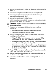
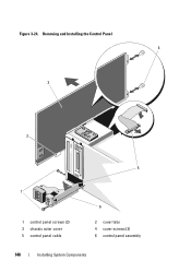
Figure 3-24. Removing and Installing the Control Panel 4 3 2 5 1 1 control panel screws (2) 3 chassis outer cover 5 control panel cable 6 2 cover tabs 4 cover screws (2) 6 control panel assembly 140 Installing System Components
Figure 3-24. Removing and Installing the Control Panel 4 3 2 5 1 1 control panel screws (2) 3 chassis outer cover 5 control panel cable 6 2 cover tabs 4 cover screws (2) 6 control panel assembly 140 Installing System Components
Hardware Owner's Manual
Page 141
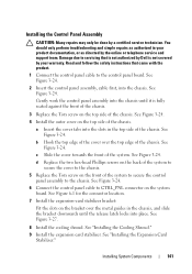
...repairs may only be done by your product documentation, or as authorized in the chassis, and slide the bracket downwards until it is not covered by a certified service technician. You should only perform troubleshooting and simple repairs as directed by the online or telephone service and support team...stabilizer. Read and follow the safety instructions that came with the product. 1 Connect the control panel cable to servicing that is not authorized by Dell is fully seated against the front of the chassis. 3 Replace the Torx screw on the top side of the chassis. See Figure 3-24...
...repairs may only be done by your product documentation, or as authorized in the chassis, and slide the bracket downwards until it is not covered by a certified service technician. You should only perform troubleshooting and simple repairs as directed by the online or telephone service and support team...stabilizer. Read and follow the safety instructions that came with the product. 1 Connect the control panel cable to servicing that is not authorized by Dell is fully seated against the front of the chassis. 3 Replace the Torx screw on the top side of the chassis. See Figure 3-24...
Hardware Owner's Manual
Page 142
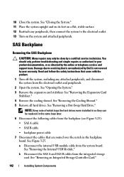
... from the backplane (see Figure 3-25): • SAS A cable • SAS B cable • backplane power cable 7 Disconnect the cables that is not authorized by Dell is not covered by your product documentation, or as authorized in your warranty. See "Removing the Cooling Shroud." 5 Remove all hard drives. See "Removing the Internal USB...
... from the backplane (see Figure 3-25): • SAS A cable • SAS B cable • backplane power cable 7 Disconnect the cables that is not authorized by Dell is not covered by your product documentation, or as authorized in your warranty. See "Removing the Cooling Shroud." 5 Remove all hard drives. See "Removing the Internal USB...
Hardware Owner's Manual
Page 144
... repairs may only be done by the online or telephone service and support team. Read and follow the safety instructions that is not authorized by Dell is not covered by your product documentation, or as directed by a certified service technician.
... repairs may only be done by the online or telephone service and support team. Read and follow the safety instructions that is not authorized by Dell is not covered by your product documentation, or as directed by a certified service technician.

